K3PGP.Experimenter's.Corner
![]()
K3PGP.Experimenter's.Corner
![]()
Home Astronomy Construction Laser Moonbounce Software Guest Misc
A
Low Noise PIN diode Laser Receiver !
- Part 2 !
By John, K3PGP rev1.3
Ever wonder what the magic is about those 100 megohm load resistors? Here's some interesting data that I found in a very old (1978!) HP OptoElectronics Designer's Catalog.
 |
 |
As you can see the noise current (under dark conditions) from the typical PIN photodiode is just about equal to the noise emitted by a 100 megohm load resistor!
The chart to the right shows the NEP (Noise Equivalent Power) as a result of BOTH sources (the dark PIN diode and the load resistor.
Keep in mind that as the load resistance is increased the shunt capacitance of the PIN diode and associated circuitry will cause the higher frequencies to roll off. For typical laser com using MCW or BPSK at 800 Hz this is not a problem when using load resistors of approx. 100 Megs or when using the MPF-102 preamp with no load resistor under nighttime conditions. However, if you need to detect short duration pulses you will need to decrease the value of the load resistor. This will increase the high frequency performance but will result in a DECREASE in SNR as you will be hearing more noise from the load resistor and less signal from the detector! Also, you may be better off with several smaller resistors in series as the shunt capacitance may actually be lower. These are usually left flying in the air away from any other components or metal parts to reduce shunt capacitance.
Please note that the above discussion pertains to working with optical signals that are near or below the noise floor! Under strong signal conditions you may need an entirely different setup depending on what you are trying to accomplish.
|
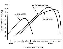
| Response of various types of PIN diodes |
Improvements?
It has been my experience that the MPF-102 preamp has no problem hearing the dark current emitted by the typical PIN diode as long as the load resistor is above 100 megohms or totally eliminated as suggested in part one of this article. Building a better preamp is NOT the answer in the quest for more sensitivity as the noise floor is being generated in the PIN diode itself!
|
| Results of cooling PIN Diodes! |
The only way I have been able to improve the reception of weak signals that are at or below the noise floor is by cooling the PIN diode. This causes a substantial drop in the noise floor. Just how far this technique can be taken is unknown, but I've heard of people running optical front ends in liquid nitrogen! So far the lowest I've tried it has been -20 degrees C which was obtained with a peltier junction. As you can see by the chart above this resulted in a very worthwhile improvement in weak signal performance and as the graph appears quite linear I assume that this technique can be used BELOW -20 degrees C with still further enhancement. Be prepared to deal with moisture condensation however, if you try this. Unfortunately very high impedance circuits and moisture do NOT mix.
PLEASE NOTE: You should be working with signals near the noise floor when making these measurements and you should be comparing the signal to noise ratio.
You can get some ideas as to how this works by sticking your PIN diode front end in the freezer. While it is cooling off have everything ready to go so you can make measurements immediately when you take it out of the freezer. You should notice quite an enhancement when you first power up the front end and a gradual drop in SNR as the diode warms back up to room temperature.
If you are really serious about this you might try mounting the PIN diode and preamp in an air tight container so that the air (and moisture) can be pumped out. Or you might try simply filling the container with desiccant. However, on the front of the sealed enclosure you will need to provide for a heated glass window. The heat can come from a couple of 1/2 watt resistors in contact with the glass. The small amount of heat generated will prevent moisture from condensing on the outside surface of the window (the side exposed to the atmosphere). The cooling can be provided with a peltier junction.
Interfacing the Laser Rx front end to the BPSK S-D board!
(Note: If you don't know what an S-D board is see references to VE2IQ on this web site! Basically it's an A/D converter than plugs into the serial port of a computer and allows the computer to extract extremely weak signals that are at or below the noise floor.)
One of the most common errors when interfacing this front end to most Rx setups is insufficient gain! You should follow the preamp with enough gain so that you can drive the S-D board to the clipping point with NO optical signal being applied to the front end. The gain is then slightly decreased to just below the clipping point. You will achieve best weak signal performance under these conditions.
As explained in part - 1 of this article, my setup consists of three TL-071 opamps in series between the MPF-102 preamp and the S-D board. These are setup as a low pass, high pass and gain stage. As I indicated before I find sharply peaked narrow band filters extremely hard to listen to and prefer the high/low pass filter arrangement. When trying to use narrow band opamp filters it was also noted that they introduced a variable phase shift as the amplitude of the signal was increased. This made distance measuring to close in targets extremely difficult as the phase shift through the Rx would change as the signal level changed! Going to the high/low pass filter / gain stage totally eliminated this effect and was also a LOT easier on the ears!
You can probably get by very well without the high/low pass filters and just provide for enough gain to drive the S-D board. I've never noticed any increase in sensitivity with or without the high/low pass filter when using the computer to process extremely weak signals. However, I did find it easier to hear weak signals in the noise once I got rid of all the high frequency hiss and low frequency hum!
I made provisions for switching mine in and out as I find it most interesting to study man made light bouncing back from various cloud layers and noting the spectral plot when using FFTZZ that comes with the software provided by VE2IQ. I have noticed that different types of light sources have vastly different spectral content (harmonics of 60 Hz) when viewed with this setup.
Closing Comments:
The above preamp / detector has been optimized for weak signal NON line of site communications, such as troposcatter and optical EME using narrow bandwidth modes such as 800 Hz MCW and BPSK. Although this preamp will provide excellent day and nighttime performance up to 20 Khz or so, the shunt capacitance of the PIN diode across the extremely high input impedance of the FET causes the gain to drop and the noise figure to get worse as the frequency is increased.
If your goal is high data rate communications, pulse or video you will either have to load the PIN diode with a low value resistor (and suffer the SNR degradation) or use a different type of preamp in order to gain more useable bandwidth. You might try running the PIN diode directly into a 50 ohm resistor and capacitively couple this directly into the second stage 2N4124 and eliminate the FET entirely. This will provide bandwidth up into the tens or even hundreds of Mhz but of course will sacrifice SNR! Remember to also decrease the collector resistor to something like 100 to 1000 ohms and redo the bias resistor for half collector voltage!
Another approach is to convert the FET input to grounded gate operation. In this case the gate is grounded and the PIN diode is connected to the source lead which also has a low value resistor going to ground. The output is still taken from the drain lead.
Several people have suggested that I could achieve better performance using a trans-impedance op-amp design. I have already tried this and have found them to be approx. 4.5 dB worse in SNR when receiving an extremely weak 800 Hz BPSK optical signal. The only type of optical detector that I have seen that has consistently outperformed this preamp/detector is a Photo Multiplier Tube (PMT). The only problem with the PMT's that I have is that all appear to suffer from red droop making them useless for weak signal work in the 780 to 830 nm region. There are PMT's made specifically for use at IR but so far I have been unable to find one. There may be a way to equal the sensitivity of some PMTs without actually using a PMT by using lower modulation frequencies. See the note at the end of this article.
I have received several Emails telling me about the various integrated light detectors such as the OP-101 / OPT-301 series. I have built several front ends based on these devices and although I consider them an excellent way to start out in light communications, for some reason they simply don't have what it takes when it comes to extremely weak optical communications. I have yet to be able to detect any form of laser troposcatter using one of these and the results using cloud bounce is noticeably poorer. I'm not sure if this has something to do with the circuitry of the device or the optical detector used. They seem to perform OK (nothing spectacular) on direct line of sight paths. However, when it comes to more exotic modes they don't seem to have what it takes. It could very well be that since troposcatter and cloud bounce result in a diffuse source instead of a point source the very small geometry of the optical detector may be the problem. Further tests are needed to determine why these devices do not perform up to expectations.
If you are primarily interested in weak signal optical communications you may want to investigate the use of lower modulation frequencies which appear to offer enhanced performance when used with this frontend. Pay particular attention to what happens to SIGNAL TO NOISE RATIO when the modulation frequency is reduced to below 100 Hz! Do NOT confuse frequency response with signal to noise ratio! In the photo below it appears that the signal to noise peaks at 20 Hz when in reality the signal to noise is highest at the lowest frequency tested, 5 Hz. The graph is misleading due to low frequency rolloff. You may need to increase the value of any coupling capacitors in the audio path if you notice this problem. After this was done I found that the signal to noise ratio continued to rise as I went below 20 Hz.
The graphic shown above is an optical signal transmitted by a single IR (880 to 900 nm) LED transmitter at 250 ma current peak current pointed straight up into the night time sky. Receiver was the front end described in this article approximately 5 miles from the LED transmitter using a fresnel lens. There is an astounding difference in signal to noise ratio at 20 Hz when compared to 800 Hz! When using 800 Hz the signal was almost always below the noise with only occasional peaks being detected. At 20 Hz the signal was ALWAYS present!
For more info on this effect see LF Optical Experiments.
Contents of this website are (c)1997-98 of K3PGP and of the originating authors.