K3PGP.Experimenter's.Corner
![]()
K3PGP.Experimenter's.Corner
![]()
Home Astronomy Bicycle Construction Laser Moonbounce Software Guest Misc
Low
Frequency Modulation Laser Experiments
- A New Weak Signal Laser Mode ? -
This
idea has been implemented in software by K0SM <LASERSCATTER> Approx. 106k
Also available on the Software page
This article is presented with the primary interest of showing what happens to a typical optical communications system when the modulation frequency is reduced and a way of using lower modulation frequencies to carry communications.. I'm hoping this will encourage other optical experimenters to experiment with modulation frequencies other than 800 Hz. Whether or not you observe the enhanced effect described may depend on the type of optical Frontend you are using for a receiver. In order to faciliate discussion of this mode it has been named PGP-1.
It seems that most DSP waterfall
displays are quite good at finding very weak carriers in the
presence of noise. Many people have taken advantage of this fact
by using schemes such as sending VERY slow speed CW and decoding
it by watching the computer screen.
One of the problems with this method is the number of transitions
needed to send just one character. Morse code requires from 1 to
7 (approx!) bits per character. ASCII is 7 or 8 bits per
character. Baudot is 5 bits per character. How about a narrow
band mode with ONE bit transition per character??? Using the
coding scheme described here the transmitter remains on ONE
frequency for the entire duration that each character is being
sent. This allows maximum throughput for a given bandwidth and
maximum detection capability using the DSP software tools that we
have available today.
 |
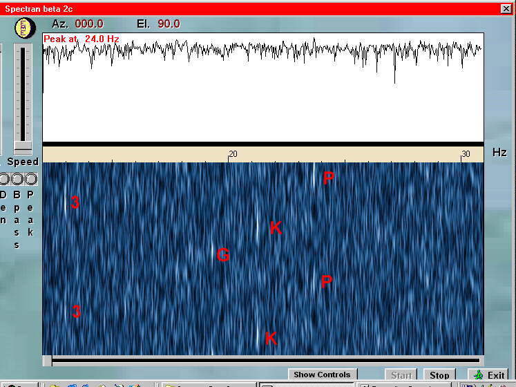
While experimenting with a simple 19 / 20 Hz FSK optical beacon and watching the waterfall displayI noticed that I could detect this signal at incredibly low amplitudes if it spent at least 30 seconds on each frequency. Making the keying period longer didn't seem to make much improvement in the detection threshold. (This could be a limitation of the software I was using or a peculiarity of the propagation path.) However, if I tried to shorten the period spent on each frequency it became increasingly harder to detect the signal. With this in mind I came up with the encoding scheme described in this article. |
There is no problem in differentiating between
signals 0.5 Hz apart even at 20 Hz using programs such as
Spectran. So why not set up a table of 26 letters and 10 numbers,
each sending on a different frequency 0.5 Hz apart??? This would
be centered on approx. 20 Hz and the total bandwidth required
would be approx. 18 Hz !
I chose 20 Hz as the optical equipment I am presently using is
MUCH more sensitve at lower frequencies than at 800 Hz. Also I
wanted to compare transmission and detection capabilities at
these very low frequencies with the more traditional approach at
800 Hz to see what effect atmospherics might have on very low
data rates carried on very low modulation frequencies. However,
this same scheme could easily be used at any frequency simply by
changing the table of transmitted frequencies so it's centered on
xxx (800 ?) Hz or wherever is appropriate for the transmitting
system in use.
As mentioned previously the transmitter spends the FULL time on
ONE frequency for each character allowing for maximum detection
capability. Although one could read the code from the Spectran
waterfall display, a suitable decoder could be implemented in
software.
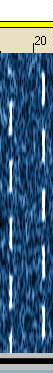
Here is an example of a VERY weak optical signal using this coding scheme:
I don't see any way to improve upon this
modulation scheme. I think it breaks the coding down to the
absolute minimum amount of transitions needed to send the
message. Of course CW at 0.5 seconds per bit would also have
worked on this path but it would have taken a MUCH longer period
of time to transmit as each character would then consist of
multiple bits and of course would also be more difficult to
decode as one would have to make sure of the bits sent and group
them correctly. The beauty of this system is once you have
decoded ONE bit on a given frequency you know the character sent
and the transmission speed is 2 CHARACTERS per minute. A vast
improvement over regular CW at 30 seconds per dot / bit.
The transmitter used to send this message consisted of a SINGLE
IR LED with 250 ma of current passing through it pointed straight
up into the night time sky. Since the keying signal is a 50% duty
cycle square wave the average current is 125 ma.)
The optical receiver was the one described at Frontend and was used with a 12 inch
fresnel lens. Distance from the transmitter to the receiver is
approx. 5 miles.
The above fsk.jpg signal
was received with solid cloud cover. Under conditions like this
almost any modulation scheme would produce solid copy. However,
the k3pg.jpg signal was
received under CLEAR SKY conditions and is EXTREMELY weak. When
signals are this weak it takes approx. 30 seconds before I can
determine whether the transmitter is on or off. Under NO
conditions could I detect this signal at 800 Hz using my present
optical receiver.
I was prompted to try experimenting with much lower modulation frequencies of lasers for communications than the traditional 800 Hz when I started to become aware that my optical receiver appeared to be MUCH more sensitive to naturally occuring low frequency phenomenon. Several people (most notably KY1K) also suggested that it might be possible to detect much weaker optical signals if the modulation frequency was lowered.
To see what might be possible I set up a test using the lowest amplitude 800 Hz laser signal that I could detect then started dropping the modulation frequency in 100 Hz steps. This produced the following graph:
Note that 800 Hz is completely buried in the noise. The signal just starts to produce a positive signal to noise ratio when the frequency is lowered to below 300 Hz with a very marked increase below 100 Hz. The SNR appears to continue to increase below 20 Hz but is not apparent in the above photo due to low frequency roll off problems in the sound card used to digitize the waveform. This problem has since been corrected.
When I first tried decoding the beacon signal I
was puzzled by what appeared to be incorrect decoding. The call
should have been K3PGP. It wasn't till the next day that I
discovered that I had made a programming error and left off the
last letter! This was very interesting to me as it proved that I
was actually hearing the transmitter well enough to determine
that it was sending the incorrect call! It is assumed that the
signal was being received via scatter from water vapor and
pollution in the atmosphere as there is no other way for the low
power optical signal to get from the transmitter to the receiver
as both were aimed up into the night time sky and were
approximately five miles apart. The LED used emits in the 880 /
900 nm region.
The only improvement I can think of in this scheme would be if we
start to encode common words or phrases. For instance a carrier
on xx Hz for 60 seconds might mean, "Got all calls and
signal reports needed to complete QSO. Roger 73 and thanks",
etc.
I think all we need are some standards on how to set this up such
as spacing in Hz between characters, length of each bit /
character in time, and of course the center frequency. A higher
frequency (the usual 800 Hz?) would be needed for radio work. Due
to all the variables possible it might be a very good idea to
make any software using this scheme fully programmable via lookup
tables as to transmitted frequencies, duration per bit, etc.
Optical communications as we know it today has one BIG advantage
in that the received frequency as received at the receiver is
almost always the same exact frequency sent from the transmitter.
However, in radio work tuning and frequency stability become an
issue. There are many stations on 144 Mhz and above where
frequency stability of less than 1 Hz is no longer a problem.
Some paths such as EME would also introduce an unknown (but
calculable) doppler frequency offset so some form of calibration
signal to line up the decoder may be needed. Maybe 1 minute of
center frequency (20 Hz or 800 Hz ?) followed by the frequency
coded message? Another possibility that comes to mind is an FSK
signal using the highest and lowest character frequencies. This
would spend equal time on both frequecies (in this case 30
seconds each) and would be followed by the message after a
suitable number of transitions to allow calibration.
Here's the lookup table from the program I used for the optical
beacon tests.
;Lookup Table
;------------------
c(95) = 110 '
c(48) = 115: '0
c(49) = 120: '1
c(50) = 125: '2
c(51) = 130: '3
c(52) = 135: '4
c(53) = 140: '5
c(54) = 145: '6
c(55) = 150: '7
c(56) = 155: '8
c(57) = 160: '9
;-------------------
c(65) = 165: 'A"
c(66) = 170: 'B"
c(67) = 175: 'C"
c(68) = 180: 'D"
c(69) = 185: 'E
c(70) = 190: 'F
c(71) = 195: 'G"
c(72) = 200: 'H
c(73) = 205: 'I
c(74) = 210: 'J
c(75) = 215: 'K
c(76) = 220: 'L
c(77) = 225: 'M
c(78) = 230: 'N
c(79) = 235: 'O
c(80) = 240: 'P
c(81) = 245: 'Q
c(82) = 250: 'R
c(83) = 255: 'S
c(84) = 260: 'T
c(85) = 265: 'U
c(86) = 270: 'V
c(87) = 275: 'W
c(88) = 280: 'X
c(89) = 285: 'Y
c(90) = 290: 'Z
The first character c(95) is a space ($20 hex) and the
transmitted frequency is 1/10 that listed in the chart so the
letter A would be 165 / 10 or 16.5 Hz. This was neccesary in my
particular case as there is a decade divider in the signal line
which feeds the transmit LED. It is configured to divide by 5
then divide by 2 to ensure a 50% duty cycle square wave is
feeding the transmit LED at all times. There is also a failsafe
circuit to prevent the LED from staying in an ON condition as
this would place 250 ma continuously through the diode and would
destroy it in very short order. No great loss but a nuisance to
change...
As the signal level increases the speed of transmission may be
increased. Under solid cloud cover only a few seconds is needed
on each frequency to decode the proper character. However, under
clear sky conditions at least 30 seconds seems to be needed to
insure detection.
NOTE: Lasers were NOT used for any of these tests as the signal
produced by the laser was TOO strong to fully evaluate this
coding scheme or to compare optical modulating frequencies under
VERY weak signal conditions.
Home Astronomy Bicycle Construction Laser Moonbounce Software Guest Misc
Contents of this website are ©1995-2012 of K3PGP and of the originating authors.