The format of the laser specifications will follow the general outline given below. (Since most of these are gas lasers many of the entries will be missing for the dye laser.)
The following notation will be used to denote input and output connections:
Duplicating (or improving on) a known commercial design rather than one from a 20+ year old article could very well result in higher efficiency and output power and better beam quality. See the section: Sam's Three Part Process for Getting Your Feet Wet in Gas Lasers for one possible approach to this.
Where possible, an attempt will be made to estimate the expected power (or at least an upper bound) based on tube dimensions, power supply, and other factors. At best this will be a wild guess but may provide some indication of the possibilities for improvement by tweaking the design.
Note that this also means that it is NOT possible to determine the laser safety classification for these lasers. They maybe of very low power but this is not guaranteed. So, treat their output as at least Class IIIb (Class IV for the CO2 laser) until you can be sure that it isn't!
Refer to Typical Home-Built Helium-Neon Laser Assembly for a simplified diagram of the overall glasswork and power supply electronics.
       H o----------+ T1                T2   +---------o HV AC
                     )||               ||=||(
              Variac )<--------------+ || ||(
              0-110V )||              )|| ||(
                  5A )||    Neon Sign )|| ||(       Well insulated
                     )||  Transformer )|| || +---+  HV wires to HeNe
                 +--+        9KV,18mA )|| ||(    |  tube electrodes
                 |                    )|| ||(    |
       N o-------+-------------------+ || ||(    |
                                       ||=||(    |
                                       |   | +---|-----o HV AC
                                       |   |     |
       G o-----------------------------+---+-----+
                                                _|_
                                               ////
A modern tube with a 34 cm discharge length would be rated about 5 mW when run from a normal HeNe laser power supply (DC, constant current).
For an HeNe tube, a wider bore doesn't necessarily permit higher power since the walls of the capillary apparently are important in depopulating higher energy levels. Therefore, I will assume that this is really equivalent to a 1 mm bore in a modern tube.
Loss factor: .5.
Loss factor: .5.
Loss factor: .5.
Loss factor: .5.
Based on these considerations, I would be surprised if the original design produced more than .5 mW. But the good news is that it might be possible to approach 2 or 3 mW without too much effort using a narrower bore, large can style cathode, and modern HeNe power supply.
As described in the article, the procedure is extremely risky. The alignment is performed with the laser powered but presumably not lasing since a 'spoiler glass' - a glass slide - is placed in the optical path. While this probably is fairly reliable for the low gain HeNe laser (but I wouldn't want to bet my vision on it!), many other lasers have high enough gain that the losses introduced by the spoiler would NOT prevent lasing and a beam could appear without warning (once the mirrors are aligned well enough) as the adjustment screws are being tweaked! I would NOT recommend the procedure as described for any laser unless a more reliable method were used of preventing accidental lasing (like the use of a 50 percent neutral density filter).
The description is also somewhat ambiguous. My interpretation is that the mirror closest to the observer is aligned first by centering the cross-hair image and then the other mirror is adjusted to center the 'moon' image. This is then repeated from the other end of the tube.
Also, using red gelatin for the viewing filter would seem to prevent observing anything about the far mirror as this would require passing red light - the same color as what the mirrors are designed to reflect best - through the closer mirror.
I would recommend using one of the other alignment techniques described in "Light and its Uses" or in the chapters in the document on HeNe and Ar/Kr lasers.
You will need the vacuum setup and a source of the HeNe gas mixture, but the serious glass working can be postponed for another day.
The basic idea will be to start off with a laser resonator that once worked (a commercial HeNe tube) using a regular HeNe power supply. Inexpensive HeNe tubes and power supplies are readily available and therefore, much of the uncertainty can be easily eliminated so you can concentrate on the gas and vacuum issues.
I would recommend something in the 5 to 10 mW range - large enough to be interesting but not so long as to possibly require magnets or other special attention to operate reliably.
Note: Don't file all the way through as this will deposit metal particles and who-knows-what-else inside the tube.
WARNING: The anode will be at a KV or more with respect to everything else! Cover, shield, or otherwise insulated it from accidental contact.
Note: For this to work, both mirrors must be planar - otherwise, the added distance between them when mounted externally will mess up the confocal relationship that would have been present where one or both was concave. Alternatively, use mirrors from a *longer* HeNe tube (though I don't know if the mirror coatings are optimized for a particular length discharge or not).
Use Epoxy to attach the windows to the tubes and let them set for a couple of days. Then clean them inside and out with denatured alcohol.
You can use a pair of identical electrodes and the AC power supply described in "Light and its Uses". However, it would also be possible (with just a little more glass-work) to provide a large side-tube (which also provides a much greater gas reservoir) and aluminum (can) cathode as in commercial tubes with a regular HeNe (DC) laser power supply.
Refer to Typical Home-Built Argon Ion Laser Assembly for a simplified diagram of the overall glasswork and power supply electronics.
                                             D1
     H o--------+ T1                T2   +--|>|--+------+------+------o HV+
                 )||               ||=||(  10KV  |      |      |
          Variac )<--------------+ || ||(        |      |      |
          0-110V )||              )|| ||(        |      |      / R1
              5A )||    Neon Sign )|| ||(        |     _|_ C1  \ 2M
                 )||  Transformer )|| || +-------|--+  --- 1uF / 3W
             +--+        5KV,30mA )|| ||(        |  |   |  5KV \ 5KV
             |                    )|| ||(        |  |   |      |
     N o-----+-------------------+ || ||(        |  |   |      |
                                   ||=||(   D2   |  |   |      |
                                   |   | +--|>|--+  +---+------+--+---o HV-
                                   |   |    10KV    |            _|_
     G o---------------------------+---+------------+           ////
Triggering could be done using any of the pulse type HeNe starting circuits described in the chapter: HeNe Laser Power Supply Design but as above using the external electrode rather than a direct connection to the tube anode. Any similar xenon strobe trigger should also work.
A modern Ar/Kr ion tube with a 50 cm discharge length would likely be rated at over a WATT when run from a high current power supply. Obviously, since this one is pulsed at a very low duty cycle, the power will be much reduced considerably.
For a HeNe tube, a wider bore doesn't necessarily permit higher power since the walls of the capillary apparently are important in depopulating higher energy levels. I don't know how this affects ion laser performance. Therefore, I will assume that this is really equivalent to a 1 mm bore in a modern tube.
Loss factor: .5.
For a 30 mA maximum source, a 1 uF capacitor can charge at 30,000 V/second best case. It is not clear at what voltage the tube will fire when triggered or how this related to actual peak laser tube current. There is no ballast resistor. In 1/120th of a second, the cap will charge to to perhaps 450 V (from a tube cutoff of 200 V).
Best case, if the energy represented by the difference between 200 and 450 V when dumped into the tube with the optimum current of, say 20 A, the pulse width would be about 15 us (very wild guess!). Thus, compared to a modern ion laser run on a DC power supply, the ratio of output power to what is possible is about 1:(1.5E-5 * 120) or about 1:555.
Loss factor: .9982.
Loss factor: .75.
Loss factor: .5.
Here is a set of questions from someone with somewhat grandiose ideas:
You probably won't end up with a sealed tube either - as it will have a very short life.
Then, you need to have a vacuum system, tubing, gauges, the appropriate gasses, a 5 A or more 100 V current regulated power supply, etc.
Light bulb filaments are not designed for emission - they are not coated. You would have to obtain a proper coated tungsten filament. And, of course, a 300 W bulb is only about 2.5 A so even if you were able to do this and sent current from both ends, you are on the hairy edge. A microwave oven magnetron tube filament might work although these are rated more in the 1 A maximum range.
I must say that I encourage you to pursue your interests and passions, but perhaps start with something somewhat less ambitious!
However, if all you want is a different colored laser, green laser pointers are coming down in price as are other Diode Pumped Solid State (DPSS) lasers:
(From: Walter Burgess).
If you want to try a different color, a green DPSS laser might be easier. An 808 nm diode laser emits into a Nd:YAG crystal (substitute Nd:VYO4 for better results). That crystal emits at 1064 nm. This is applied to a KTP crystal which doubles it to 532 nm which is green colored light.
If you decide to attempt the argon ion laser, I would probably recommend using bore closer to 1 mm since this should assure TEM00 mode operation and is more typical of a commercial ion tube. Then, the current thresholds should be similar as well.
Its output is at 10.6 um (10,600 nm) or mid-IR. This wavelength is about 10 to 30 times longer than the other lasers under discussion and often considered a source of a heat beam than a light beam. At this wavelength, normal glass and plastic optics are either too lossy or totally opaque so alternatives must be found both for the end-mirrors and any other mirrors, lenses, or prisms required by the external optical setup. Divergence/diffraction effects are also increased by this same factor so obtaining a collimated beam is also more difficult.
Many common materials including wood, paper, plastics, composites, and properly prepared metal surfaces absorb quite well at this wavelength so the CO2 laser makes an effective marking, cutting, welding, and heat treating tool.
See the chapter: Carbon Dioxide Lasers for more information on the characteristics and applications of these devices.
It is possible for an amateur to construct a working CO2 laser in the 10 to 50 W range without too much difficulty - at least compared to some of the other types. A vacuum system is needed but the range of operating vacuum is modest - 10 to 100 Torr. And while several gasses are needed, the purity of the final gas fill isn't nearly as critical as for, say, the HeNe laser. With a bit of resourcefulness, no fancy glass work is needed. The power supply can be just a neon sign transformer on a Variac.
My only complaint about CO2 lasers in general are that the beam is totally invisible and boring in some ways. :-) Otherwise, it is nearly the perfect choice for a home-built laser - high power, continuous operation, and relative simplicity!
However, constructing a CO2 laser is still NOT easy in an absolute sense and you have to make a considerable commitment of time and effort in locating parts and materials, setting up your vacuum system and gas supplies, fabricating the tube and water jacket, constructing the power supply, and putting it all together, or you will end up with a box full of parts and equipment gathering dust in the attic.... :-(
This includes plans for a HeNe power supply as well as complete ruby/Nd-YAG and CO2 lasers and other interesting stuff. See the section: Iannini CO2 Laser Description for more information.
The summary below is for the CO2 laser from "Light and its Uses". Also see the section: Iannini CO2 Laser Description.
Refer to Typical Home-Built Carbon Dioxide Laser Assembly for a simplified diagram of the overall glasswork and power supply electronics.
CO2 can be easily obtained from dry ice; N2 from filtered air (despite the presense of O2 and other trace gasses) apparently works well enough.
                                                         D1
         H o--------+ T1                T2   +--------+--|>|--+---o HV+
                     )||               ||=||(         |       |
              Variac )<--------------+ || ||(         |  D2   |
              0-110V )||              )|| ||(      +--|--|>|--+
                 15A )||    Neon Sign )|| ||(      |  |
                     )||  Transformer )|| || +--+  |  |
                 +--+      12KV,100mA )|| ||(   |  |  |  D3
                 |                    )|| ||(   |  |  +--|<|--+
         N o-----+-------------------+ || ||(   |  |          |
                                       ||=||(   |  |     D4   |
                                       |   | +--|--+-----|<|--+---o HV-
                                       |   |    |
         G o---------------------------+---+----+
                                               _|_
                                              ////
The laser can be operated on the raw output of the neon sign transformer (AC)
but the efficiency and maximum power output may be lower (though it isn't
entirely clear why this should be the case since the discharge current is
varying in the same manner for both cases). With the addition of some
filtering and a regulator and/or ballast resistor, the optimal current could
be maintained continuously boosting efficiency and power output. However, a
starter like a high power version of that used for modern HeNe laser tubes may
be required. See the HeNe power supply information in the sections beginning
with: Starters - Voltage Multiplier, Pulse, Inverter, Piezo.
Although generally similar to the CO2 laser from "Light and its Uses" (see the section: Home-Built CO2 Laser Description, it is more than twice as long and should therefore be capable of much higher power operation. Some glass working is specified (though this could easily be avoided with minimal design changes) and the power supply has more frills (but is only AC instead of DC and therefore will not be as efficient).
My original CO2 laser and power supply is pretty much along the lines as the Scientific American as described in the section: Home-Built CO2 Laser Description
I have recently built a smaller and more compact power supply for it. This consists of a 9,000 volt, 30 mA neon sign transformer, manufactured by the Canadian firm of Allanson, as the basic unit. This is the type of transformer with the two high voltage terminals coming directly out the top of the tar insulation, all enclosed in a somewhat larger metal case. This case left plenty of room for a bridge rectifier, key switch, fuse, 'on' light, milliameter and a 3 amp Variac. A six foot 3-wire appliance cord with IEC input module and two 20 inch high voltage output leads, with color-coded alligator clips complete the package.
This power supply seems to perform as well as the 15,000 volt @ 60 mA unit that I had employed in the past with this modest sized laser. I no longer have a supply of commercial CO2 laser gas and have been using the 'three separate gas' system for some time now with good success. I have been using a commercial cylinder of compressed helium (useful for most other lasers also), nitrogen from the air (bubbled through water) and sublimating dry ice for the CO2 supply. I had bought a small supply of dry ice on Friday which lasted only until Saturday evening, due to its tendency to mysteriously disappear even when stored in an insulated cooler. Out of sheer curiosity today I decided to try a much more readily available source of carbon dioxide gas to operate this laser with. Searching through the cupboards I found some white vinegar and a small box of baking soda. Lo and behold, a small amount of this mixture in a flask produced a fine source of CO2. I was pleasantly surprised to open the needle valve from this flask to the laser and see a fine burn pattern appear on my thermal FAX paper target. No more dry ice! I just thought you may wish to pass this on to the amateur laser community. This really simplifies the gas problem for small CO2 lasers.
I am not sure of the power output I am getting with this system, but it will easily ignite the FAX paper in a matter of five to ten seconds without any focusing optics. The burn pattern is quite large also with this wide bore (1 inch) plasma tube. I have read about your plan for measuring CO2 output power by heating a measured quantity of water for ten minutes. I have yet to try this yet, basically for lack of a suitable reflector to steer this beam into a container. I have a simple thermometer with a flat black penny attached to the stem to see temperature rise from the beam impinging upon said target. This allows some comparison of output power, but is there anyway to translate this to watts? I am getting about a one and one half degree centigrade rise in temperature per second at full power.
(From: Sam).
Yes, by knowing the mass of the penny (about 5 grams I think) and the rate of initial rise in temperature, you should be able to calculate the approximate beam power. What you need is temperature rise/Joule (or calorie) of energy for a standard penny. :-) I say 'initial' since losses due to convection and radiation of the heat energy will be small. This is still going to be tricky without a serious effort to insulate the 'sensor'.
Since water is a good absorber of 10.6 um radiation, a simple 'water heating test' like that used to evaluate the performance of a microwave oven should be able to determine the actual power in the laser beam to a fair degree of accuracy. To do this, provide a way of directing the beam from your CO2 laser downward - a polished copper plate used a mirror, for example. Place 100 ml of water in a small thermos (dewer) and measure its temperature. Run the CO2 laser beam into the water for 10 minutes. Then, the power in the beam is given by: P(beam) = Temperature rise in DegC multiplied by .7. I do not know to what extent the reflectivity of the water will affect these readings but the experiment is easy enough!
I'm considering a project of building a small CO2-laser. I have a fully reflective mirror (germanium with gold coating) and output-coupler (transparent material with gold coating) from a 500 W laser. These mirrors are old but usable according to the person who kindly gave them to me from a company doing laser-cutting.
(From: A. E. Siegman (siegman@ee.stanford.edu)).
The output coupler is possibly zinc selenide (expensive); coating probably is *not* gold, but a gold-colored dielectric coating.
If mirrors are salt (NaCL) (they'll be quite light in weight) keep 'em dry!
(From: Kristian Tapani Ukkonen (kukkonen@epsilon.hut.fi)).
I have plans for a CO2-laser (from "Light and its Uses" but several questions do arise: The article does not really comment the ratio of discharge tube length to the diameter and how to correlate this to optimal performance and pressure and ratio of gasses. They do mention about 18" long and 1" diameter tube with 1-20 torr and 8 parts He, 2 N2 and 1 CO2 while with narrower tube higher pressures apply. Their efficiency is rather low (about 1%) while I've read even 30% can be achieved. Why would this be - does errors with pressures and tube dimensions cause this? They do use 12 kV 0 to 100 mA to drive the tube with <10 W output.
(From: A. E. Siegman (siegman@ee.stanford.edu)).
CO2 insensitive to tube diameter; gain goes up linearly with length. 1" diameter is largish; 1 cm more common; 18" length is quite short; 60 cm to 1 m might be more like it.
Power output per unit length is almost independent of tube diameter (larger tube has more gas, but gas gets hotter because of longer diffusion length to walls, and so you don't get more power).
Optimum pressure, mixture and discharge conditions probably best determined by trial and error. There are probably known recipes for optimum conditions, but still, trial and error is the easiest way to go.
(From: Kristian Tapani Ukkonen (kukkonen@epsilon.hut.fi)).
Sputtering to mirrors. The article has the mirrors directly mounted to the ends with bellows of brass as means to align them. I'd guess that the mirrors get destroyed by sputtering at least at one end?? In order to prevent this I've thought about using bi-sectional tube with middle grounded and either +V or -V at both ends. Would this help? What is it that really is the threat - ionized electrode material? I've planned using stainless-steel. I'd rather than mount mirrors to direct contact to plasma do use some windows at ends and mirrors at some distance away - does this sound reasonable or will I face problems - if not what would be a good material for the windows and do they have to be at brewster angle - I've seen some designs of high-gain lasers that do not use angled windows.
(From: A. E. Siegman (siegman@ee.stanford.edu)).
Be careful!!!! Bellows could be hot electrically, and even if you think bellows are grounded, discharge could jump to mirrors.
I shouldn't give advice on this, because I really don't know, but I have the impression the CO2 laser discharge is a fairly 'soft' glow discharge, and doesn't do a lot of sputtering or damage to mirrors.
CO2 gain fairly low; if not intracavity mirrors, then Brewster windows essential. Large salt flats possible, but fragile; big ZnSe slabs best but pricey, and angle is very steep.
(From: Kristian Tapani Ukkonen (kukkonen@epsilon.hut.fi)).
I do use a 220 VAC:20 KV 7KW externally current-limited transformer for this project. I can control both voltage and current with Variac and adjustable inductance -> 0 to 20 kV 0 to 350 mA
(From: Sam).
That sort of power supply is gross overkill for a small CO2 laser and very dangerous. I would recommend using a luminous tube transformer as suggested in the article - still very dangerous but not quite as instantly deadly.
(From: Kristian Tapani Ukkonen (kukkonen@epsilon.hut.fi)).
Laser cavity shall be constructed using pyrex-tube with stainless-steel ends (electrode/window-holder/adjuster) and plastic water-jacket around the glass tube. Vacuum is maintained with mechanical 2-stage pump.
I can put a focusing lens after completing the laser.
                       Water
                  _      In           Water Jacket        _
         Mirror  | |_____||____________________v_________| |  Mirror
           ||    | |________________.__._________________| |    ||
           ||     I ________________|__|_________________ I     ||
           ||    | |_________________||___________  _____| |    ||
                 |_|                 ||           ||     |_|
              Electrode          Ground and     Water Electrode
                                 Vacuum Pump     Out
The gas-feed is at the end-electrodes, vacuum-pump connected to middle.
(From: A. E. Siegman (siegman@ee.stanford.edu)).
In chemical glassware catalogs you can find water cooled straight distillation columns in meter lengths. These make a good cheap water-cooled CO2 laser tube.
(From: Kristian Tapani Ukkonen (kukkonen@epsilon.hut.fi)).
Any other comments welcome.
Just to limit the amount of safety concerns: I have experience about high voltages (even Tesla-coils) and shall use adequate protection to IR protective goggles and IR camera to view beam-lines. I'm no mad scientist but an amateur with real need to a cutting laser.
The problem is that there are such a wide variation in what it will cost to obtain things like vacuum pumps that it is hard to put prices on a completed laser. Depending on your resourcefulness, scavenger ability, and luck, it could be less than $100 but it could also be a lot more. But, if you haven't anything set up now, there will be serious additional overhead. An adequate vacuum pump could easily blow the budget right there.
(From: Joe or JoEllen (joenjo@pacbell.net)).
Yes it possible to build a medium to high power laser with a limited budget but even the best scrounge would have a tough time doing it for $100! I started building a multi-watt CO2 laser years ago but had a hard time maintaining mirror alignment during pump-down (the corner-cutting design is to use the end mirrors to seal the resonator in lieu of ZnSe brewster windows used in the commercial versions.
BTW, I also started building the argon laser featured in the same book.
(From: Dave (dave-a@li.net)).
I work for a CO2 laser manufacturer (name withheld) and it depends on what you want to cut with it.
You'll need laser gas mix (on the cheap side), three flow meters (expensive), and then either nitrogen or oxygen to cut depending what you are cutting, polarizing mirrors, output mirrors, etc, etc. Its going to be expensive anyway you look at it. What are you trying to cut? And how much wattage?
(From: Christopher R. Carlen (crobc@epix.net)).
On first note, if you are not experienced with electronics, you should know that a CO2 laser power supply is VERY DANGEROUS. The high voltage and high current involved can quickly kill you. There will be absolutely no room for error. Get acquainted with basic electronics, and then electrical safety skills before setting out to build a laser power supply.
My plans for building a CO2 are not really plans, but rather practical engineering formulas that come from a declassified old CO2 laser manual from the U.S. Air Force's early experiments with CO2 and CO laser technology for Star Wars applications.
My purpose for building the thing is, well quite simply, my professor told me to do it. He wants a CO2 on a long rail which will allow the cavity length to be adjusted over a large range to demonstrate laser concepts to optics students. Plus, it should be a whole lot of fun, and a good experience for me.
If you want to cut stuff, I would recommend a commercial CO2 or Nd:YAG laser, from the surplus market, like from MWK Industries. Currently you can get something in the $1500 to $5000 range that will do the job, and you will avoid a great deal of time invested in building your own which might turn out to be disappointing, or worse, deadly if you aren't sure what you're doing.
With respect to the cost of components alone needed to build your own CO2 laser, you must consider:
Well I would be highly surprised if anyone could really build a CO2 for $100 as mentioned at Information Unlimited. You must understand that they are a dealer in some good information, and much highly suspect information.
(From: Dave (dave-a@li.net).
Damn that's cheap! The CO2 (4.5 or 4.8) usually goes for a lot more then that! Better the gas, the longer your optics will last. The N2 and He are the cheap ones (compared to CO2). I just went through this with a customer. He bought 4.0 CO2 and there was a *major* jump in price to scientific grade (4.8 I think it was. 99.998%) The 99.99 wasn't good enough. Though he should get away with premix (Mazack I now uses/used premix).
But you're right, buy a surplus 'head' its cheaper. Plus you now have a working unit that you can modify to tweak up the power :).
Refer to Typical Home-Built Nitrogen Laser Assembly for a simplified diagram of the overall structure and low voltage operated inverter type power supply electronics.
The Blumlein circuit is approximately equivalent to the following:
                  R1                L1
          - o----/\/\------+-------CCCCC-------+--------+
                           |                   |        |
                           +--------> <--------+        |
         20 KVDC       C1 _|_      Laser      _|_ C2    v SG1
                          ---     Cavity      ---       ^ Spark Gap
                           |                   |        |
          + o--------------+-------------------+--------+
The HV power supply charges both capacitors to nearly 20 KV. When the spark
gap breaks down, C2 is shorted out and the full voltage on C1 appears across
the gap along the length of the laser cavity instantly causing the nitrogen
gas to ionize. (Actually, the voltage pulse hits the center of the cavity
first and spreads to the ends in a couple of nanoseconds!) R1 simply isolates
and limits current from the HV power supply - its value is irrelevant when the
spark gap triggers!
Note: The drawings in "Light and its Uses" are at the very least confusing and may be wrong in some aspects of the description of operation of the Blumlein effect.
You won't find the PCB material at Radio Shack but it should be available at reasonable cost from surplus electronics dealers or PCB fabrication houses. However, tracking down one in your neighborhood may take some finger or leg work. Here are a couple of sources found in the Portland, OR, area, for example:
(From: Scott & Pat Chewning (patch@europa.com)).
WARNING: Handle and dispose of used etching chemicals responsibly - depending on type, they may stain or eat pipes (copper drain lines!!!), masonry and other building and landscaping materials, as well as human flesh. Read and follow all package instructions.
For the Blumlein capacitors as specified for the N2 laser, proceed as follows: Taking care not to penetrate the copper, use a sharpened nail or awl to scribe lines on the *surface* 2 cm from all 4 edges top and bottom, and another pair of lines front to back across the board 5 cm apart on the top only for the gap between the two plates. Then, use an Xacto knife or razor blade to lift the copper from the from the board at a corner or edge. The copper can be peeled from the board to back to these lines and then flexed back and forth to break the copper. I don't know what, if any, latent surface damage may result from this approach. Therefore, the chemical etch is preferred if you can stand the mess!
The puncture voltage for acrylic plastic (Plexiglass) varies between 450 and 990 volts per mil (.001") depending upon the quality of the product. Common 1/8" (.3 cm) thick sheet (assuming the lower value for puncture voltage) should be able to withstand over 55,000 volts; 1/16" sheet (.015 cm) will handle over 25 KV which is still adequate. The problem that you will encounter is the low capacitance obtained with the same surface area of even the thinner Plexiglass material (compared to the .015" (.04 cm) Fiberglass-Epoxy (though as noted above, that thickness may not be quite enough to withstand 20 KV). The dielectric constant for Plexiglass is also lower and with the increased thickness results in much less total capacitance. Stacking additional layers may not be a viable option due to the nanosecond timing requirements!
What about using discrete capacitors? You are, of course, welcome to experiment. However, I might suggest that starting with something that is known to work would be prudent even if it takes a little longer to find the proper materials. Homemade capacitors made from 10 or 100 or whatever of 1 or 2 KV units in series-parallel is asking for trouble especially in a rapid discharge circuit like this. The inductance of the leads alone will probably greatly slow the rate of discharge. Any inequality in capacitance and even how they are connected will result in voltage differences across the capacitors so they may fail immediately if not sooner. Even commercial high voltage capacitors may be inadequate. And, distributing enough of either type of discrete capacitor in just the right locations to simulate the discharge wave of the Blumlein device could prove quite a challenge in its own right! >
(Responses from: placayo@hotmail.com) unless otherwise noted).
I had it in the back of my head that input amperage also mattered somehow. In this case, milliamperes as generated by the usual laser power sources Van de Graafs and Wimshurst machines put out mere microamps. On the other hand, the nanosecond switching in Blumlein's pulsar (such as in the Scientific American column) guarantees an avalanche of current at high voltage in the laser channel. So, input current is not really critical.
Or he could have gone the simpler route and used air as the lasing medium. I understand that air lases (even at normal pressure) when used in a traveling wave laser. It's a more likely scenario. They were tireless and thorough experimenters back then to a degree we rarely find today. Some busy-body, Old Ben perhaps, may have slapped together something resembling the Blumlein switch, just to see what happens, fired it up, watched a curious fluorescence in the long notch on one Leyden jar plate or capacitor plate, packed up and went home. He wouldn't have an idea that he had just invented a laser because the output is UV and invisible.
There'd be no record of it consequently. And history slips through his fingers. If the would-be inventor had been Ben Franklin, the device would look exactly as it does today. At one point, Franklin preferred flat-plate capacitors in his work. He popularized them. They called them "Franklin squares", I think.
The traveling wave laser is one example of a technology that was sought for because it was predicted by established theory. But because of its simple construction, it could just as easily be the sort of thing that might have been invented by accident way before -- and ignored.
Or what old, "obsolete" inventions or long-discarded ideas might be resurrected with the benefit of today's know-how and materials.
(From: Sam).
Of course, in Ben's time, there was no way to realize that laser action was taking place or that such a thing was different than ordinary light anyhow, no obvious way to see UV, or reason to even check for it.
For one to claim that an invention was created they either have to have sought it out before hand or understood the ramifications of the results of a fortuitous experiment. Neither of these were really possible for another couple of centuries. :-)
Charging current is irrelevant except to the extent that it affects the repetition rate and to overcome electrical leakage in the setup (which can be quite minimal).
In fact, in the article, they suggest alternatives - their little transistor ignition coil thing and a neon sign transformer. It just affects the repetition rate. The transistor circuit probably puts out order of 10 uA at 20 KV (they say 1 percent efficiency!). A neon sign setup, perhaps 2000 times this. When the spark gap fires, the current available from the charging source is of no consequence.
It would be interesting to connect a Van De Graff or Wimhurst machine to such a setup.
(From: Chris Chagaris (pyro@grolen.com)).
Well yes, I have fired my nitrogen laser by using my Wimshurst machine as the charging source. I just tried this on a whim, and it worked. It does take a little while to get the capacitors charged to firing potential though. It is a nifty combination of the old and the new.
I followed the development of nitrogen lasers from their beginning. You will find most of the articles in Journal of Physics E Scientific Instruments in about 1968 to 1975 but that was a long time ago. The dates are ballpark. Nitrogen lasers can be used at atmospheric pressure with a helium nitrogen mix. Sulfur hexaflouride changes the near ultraviolet lifetime. The length is limited to about three feet in some designs with power output in the MEGAWATTS. They can be more than a glorified flashtube. The voltages, RF, flash, in short nearly everything about some of the designs can be deadly or permanently maim you. The cavity and capacitor are simple but must be used with the utmost caution. Study in depth first - then build!!!!!!
(From: Jon St Clair (Jon_St_Clair-QJS006@email.mot.com)).
I had a friend that made one of these once, but I never saw it operate.
It was a remarkably simple device and consisted of two sheets of metal separated by a dielectric like a sheet of Plexiglas. The lower sheet, viewed from the end, was shaped like the letter "J" laying on its back. The upper sheet was positioned so that a spark gap formed between the hook of the J and one edge of the upper plate.
The spark gap was covered on top with plastic so that nitrogen could flow along the spark gap. The spark gap was slightly more narrow on one end than the other.
When a DC high voltage charged up what was essentially a parallel plate capacitor, a nitrogen arc forms at one end of the spark gap. At least one photon of UV causes ionization of the nitrogen right next to it line with the spark gap and results in a spreading out of the discharge along the length of the spark gap.
The spark starts at one end of the gap, propagates at the speed of light along the gap adding energy to a coherent packet of photons as they travel along the gap. I am not clear on this, but I think that the pulse width of the laser may be equal to the length of the spark gap divided by the speed of light. This is a very very short period of time, and if the conversion efficiency of the energy stored in the parallel plate into coherent UV is some reasonable amount(?) then the peak power could be huge. x-Watts/second divided by a very small number of seconds!
I think obtaining a source of nitrogen and finding a optically clear (at the UV wavelength) and distortion free lens for one end of the spark gap was the only hard stuff other than building a high voltage DC power supply (and that is not hard).
When you hook up a continuous DC supply, you get a burst, it charges up again, bursts, charge up again etc. I understand it will really light up UV dyes some distance away.
(From: Dr. Peter Schellenberg (peter.schellenberg@physik.uni-ulm.de)).
Among the lasers described in "Light and its Uses" and other Amateur Scientist articles, I guess the nitrogen laser is the cheapest one, since you do not even need mirrors, and can go around with some handmade stuff and school equipment. The electrical discharge is done by a home-made capacitor in a so-called Blumlein arrangement. (Something similar can also be done to build a CO2 laser. However, in this case you need mirrors, preferentially gold mirrors. Don't be shocked, these are not that expensive).
By using a cylindrical lens, you can focus the beam from the N2 laser in a cuvette with almost any dye and get superradiant laser emission from it.
There are also a lot of descriptions for laser construction in the following scientific journals:
I prefer older articles, lets say between 1965 and 1980, some of the lasers at that time were not as complicated (and expensive!) as later designs.
Note that there are only few lasers that can really build with less than a few 100$.
(From: Richard Alexander (RAlexan290@gnn.com)).
Building a good nitrogen laser is almost trivial, and low-cost. All you have to do is send a 100 KV arc across a spark gap in a moderately low pressure (100 torr, a little more than 1/10th atmosphere) nitrogen environment. The output is crude, but $15,000 nitrogen lasers don't make a much better beam than a $200 device (the difference between the two appears to be versatility and electrical noise suppression).
(From: Chris Chagaris (pyro@grolen.com)).
I have just re-built my N2 laser and have substituted a PVC pipe in place of the plexiglass box. This withstands the vacuum much better than the box design. The box would contract whenever the vacuum was applied and was prone to leaks. I have recently obtained a cylinder of compressed nitrogen gas (for free!) to use in this laser. With the leak-proof construction and the pure N2 gas, the output of this laser has increased dramatically. I have no way of measuring the output power, but when the beam strikes a fluorescent piece of paper, it is so bright that it is somewhat uncomfortable to look at. UV protective eye ware is worn at all times, but these are clear to visible light.
I am in the process of building a small dye head to be pumped by the output of this N2 laser. I have heard that many of the dyes will 'lase' superradiantly when pumped by such a source. As these dye heads are of simple construction, I will build some with resonant optics and some without. This should be a very interesting area of experimentation.
(From: Frank Roberts (Frank_Roberts@klru.pbs.org)).
The supply needed to excite a nitrogen laser is basically a capacitive-discharge DC supply. The high voltage AC from the transformer is diode-rectified to DC and then applied across a suitably rated capacitor. Since a 15 kv neon sign transformer is rated at 15 kv RMS (average), the actual peak voltage from the transformer is greater than that by a factor of the square root of two (1.414). This means that a 15kv transformer will charge the capacitor up to 15 KV x 1.414, or over 21 KV. This is plenty of oomph for a Nitrogen laser. Be careful, this voltage applied across a capacitor is deadly! If you need more voltage, two diodes and two capacitors can be connected in the form of a voltage doubler. Your 15kv transformer will now provide 42.42 kilovolts of pump energy. You'll find that these voltages, capacitors and diodes can become expensive. One way around this is to connect your neon transformer to a relatively inexpensive voltage tripler. These are used in some color TV sets to get the 30 to 45 KV needed for the picture tube. These are potted modules containing all the capacitors and diodes in one unit. You can salvage them from broken TVs or buy them new at any electronics parts house.
Boosting the high voltage or capacitor size isn't the way to go. Increase the length of the laser tube itself to a meter or so and then move the Blumlein spark gap to one corner to introduce a traveling wave so the gain follows the coherent light down the tube.
(Replies from: Roland A. Smith (see.www.lsr.ph.ic.ac.uk@web.pages)).
I've a big problem. I have to build a Nitrogen-Laser for school. I got a scheme to build something like that in the Scientific American. It's based on the Blumlein-effect.
  +7kV              ______ooooo______
         ___________|____>  L  <____|__________________ Spark gap
          xxxxxxxxxxxxxxxxxxxxxxxxxxxxxxxxxxxxxxxxxxxx '
  -----------------------------------------------------+-------------
   0V
xxx is Epoxy-circuit-board --- is copper
> L < is laser chamber ooooo is inductor
Sorry for that terrible scheme! :)
Ok, but now the PROBLEM!!
If i'm firing up the system, it doesn't want to create any kinds of laser radiation. I'm despairing!! PLEASE HELP!!"
I have built a few of these in my time (and have run this project for first year undergrad students), and there are some critical points to watch out for. First off, SAFETY, these things can kill you if you get a good solid shock from them, so take care and follow all the usual high voltage handling guidelines. If you or your supervisor haven't done HV work before, then I strongly suggest you get someone who has to look over your working practices etc. Make very sure the PCB capacitor and power supply are properly discharged before you go near it. Remember that 7 KV can jump a fair way across surfaces to fingers etc.
Ok, with that bit out of the way, you need to check the following points.
(From: (gary@astro.as.utexas.edu)).
Subject: 1 MW N2 laser for sale $1 per pound.
Date: 08/25/97
I have this mondo 1 Mw peak N2 laser that weighs in at 1200 pounds. It is in plug-and-play condition complete with documentation. All you need is a source of nitrogen. I have a dewer and bought some LN2 and used the boil off to run the laser. Most impressive!! It made everything that was even remotely fluorescent in my garage glow intensely. I had planned to use it to pump some fluorescent plastic for a down converter to coherent visible light but I have lost momentum and want my garage back.
I want to sell the laser for $1,200. I can supply copies of the manual and photographs to anyone that is interested. It has a rather small vacuum pump that will allow 5-10 Hz rep rate but it can sustain a much higher repetition rate with a larger vacuum pump. The laser was manufactured my Molectron and is a model UV1000.
There are some other chuckles along the same lines awaiting you as links from its parent page as well.
Serious note (sort of): Aside from the obvious danger involved in obtaining the needed power supply, this is not likely to work in any case. Due to the self limiting behavior of the nitrogen laser emission characteristics, the electrical discharge would need to be precisely timed to travel along the laser tube at roughly the speed of light as in the normal Blumlein power supply rather than simply blowing a modest size crater in a one location. The required Lightning Bolt Control board (RISC microprocessor based, of course) would be one of the many major challenges of this design.
(Portions from: Brian (LOGICWIZ@prodigy.net)).
I have an idea for building a GigaJoule laser out of simple materials. The power source might seem outlandish at first but very viable in the end. This laser would be based upon the nitrogen laser. It would be constructed out of a glass or PVC pipe 4 inches x 100 feet evacuated to 25 Torr filled with nitrogen gas from probably LN or a decomposition reaction and the electrodes will be made out of band saw material (because it stands heat real well). The laser would be operated in a thunderstorm. You already know how to attract lightning using wires attached to rockets. I estimate its power to be equal to about 14.8 GigaJoules based on the charge and voltage of your typical lightning bolt and the expected (very precisely computer) efficiency of a nitrogen laser:
Refer to Typical Home-Built Helium-Mercury Laser Assembly for a simplified diagram of the overall glasswork and power supply electronics.
                                                    D1
    H o--------+ T1                T2   +--------+--|>|--+--+-------+---o HV+
                )||               ||=||(         |       |  |       |
         Variac )<--------------+ || ||(         |  D2   |  |       |
         0-110V )||              )|| ||(      +--|--|>|--+  |       /
             3A )||    Neon Sign )|| ||(      |  |         _|_ C1   \ R1
                )||  Transformer )|| || +--+  |  |         --- 10nF / 100M
            +--+        9KV,20mA )|| ||(   |  |  |  D3      |  15KV \ 5W
            |                    )|| ||(   |  |  +--|<|--+  |       | 20KV
    N o-----+-------------------+ || ||(   |  |          |  |       |
                                  ||=||(   |  |     D4   |  |       |
                                  |   | +--|--+-----|<|--+--+-------+--o HV-
                                  |   |    |
    G o---------------------------+---+----+
                                          _|_
                                         ////
Refer to Typical Home-Built Helium-Mercury Laser Assembly for a simplified diagram of the overall glasswork and power supply electronics which should be similar except for the dimensions.
(Specifications from: Garrett Hansen (gldhansen@worldnet.att.net)).
                                                 D1              Spark Gap
 H o--------+ T1                T2   +--------+--|>|--+--+-------+--> <---o HV+
             )||               ||=||(         |       |  |       |
      Variac )<--------------+ || ||(         |  D2   |  |       |
      0-110V )||              )|| ||(      +--|--|>|--+  |       /
         15A )||    Neon Sign )|| ||(      |  |         _|_ C1   \ R1
             )||  Transformer )|| || +--+  |  |         --- 20nF / 100M
         +--+       15KV,60mA )|| ||(   |  |  |  D3      |  35KV \ 25W
         |                    )|| ||(   |  |  +--|<|--+  |       | 35KV
 N o-----+-------------------+ || ||(   |  |          |  |       |
                               ||=||(   |  |     D4   |  |       |
                               |   | +--|--+-----|<|--+--+-------+--------o HV-
                               |   |    |  D1-D4: HVC1200
 G o---------------------------+---+----+
                                       _|_
                                      ////
I am just about to finally complete a mercury vapor laser as per the SciAm plans. All that I have left to do is polish flat the brewster angle cuts at either end of the plasma tube so my quartz windows will fit snugly. I am looking forward to many hours of exciting experimentation with this rare type of laser. I will get some pictures of the completed system to you as soon as I can.
I gather from the "Light and its Uses" HeHg laser description that while the laser produced 'intense pulses of green and red light', the average output power wasn't more than a mW or so. Even a 1 mW of 567 nm green would appear quite intense - 4 or 5 times brighter than 1 mW of 632.8 red.
Also see the section: Comments on HeHg Lasers.
However, a tube full of mercury vapor at a couple of Torr is not much material so a drop of mercury should go a long way. In addition to losses out the vacuum system and by condensation on the tube walls, some may form an amalgum with the metal of the electrodes or their lead-in wires (depending on the metals involved), be adsorbed by the tube walls or Epoxy seals (if used), or be buried under sputtered electrode material.
Also see the section: Comments on HeHg Lasers.
Just off the top of my head, I'd say the problem with it is the mercury. That is toxic stuff, and it goes right through your skin. Make it a vapor and you would breath it. The less you fool with it, the better off you are.
Another problem might be that mercury is expensive. A pint jar of mercury would be worth hundreds or thousands of dollars (well, a lot, anyway). The same amount of copper would be worth only a few dollars.
(From: David Demmer (ddemmer@physics.utoronto.ca)).
Nah, in an earlier life I was a chemist, and demonstrated a physical chemistry lab that used a Toppler pump. For the uninitiated, this consists of some ingenious glassware and about 500 mL of mercury. The stuff is really pretty cheap when bought in quantity: actually about $100/kg for reagent grade from Aldrich. Of course a kg is a smallish volume because it's surprisingly dense stuff.
As for a laser like a helium-mercury vapour laser, the amount of mercury necessary is actually pretty small. And besides, expense doesn't stop anybody using a gold vapour laser. The cost of the fill is trivial compared with capital and other operating costs.
Toxicity, too, never stopped anybody from using HF, F2, etc. in their excimer lasers.
So, while not knowing the answer to the fellow's question, I guess I'm saying that I don't agree with yours.
(From: Richard Alexander (RAlexan290@gnn.com)).
Well, it looks like you pretty well stopped my argument for the expense, but I think toxicity is still in play. In defense of that argument, I present my belief that excimer lasers are used mostly in industrial settings, away from most people (ok, I know there are medical excimers that offer some interesting promise).
Maybe it's not too late for me to agree with the other poster that the wavelength put out by a mercury vapor laser is better produced by another type of laser. (I've had this discussion before, several years ago. It's just taking time for me to remember what I was told.) It seems like it isn't worth the bother of making the laser when HeNe and Argon Ion cover whatever the Hg vapor laser will do (ok, I admit I don't remember what lasers cover the Hg vapor laser wavelengths. You get the gist of my hazy memories.)
(From: Herman de Jong (h.m.m.dejong@phys.tue.nl)).
Mercury is used in home used thermometers, in thermostat switches for heating the home, in tilting switches, in high power reed switches, in TL end related light tubes etc.
The mercury laser uses maybe a few milligrams/year and it could be trapped in an amalgam with silver, copper, zinc, not iron, about the only exception. this effectively blocks mercury from reaching the pump.
A thermometer contains maybe a few hundred milligrams this is no problem.
(From: Herman de Jong (h.m.m.dejong@phys.tue.nl)).
I agree with you David.
If I remember right the CW laser wasn't peculiarly intense but it had low (single ended) optical feedback and the length of the vapour was a few feet. and it was a DC discharge at a few KV with a neon transformer. It needs a Helium flushing bottle and a vacuum pump. At that wavelength it probably can't compete with the more powerful Ar+ lasers (514 nm, some are sealed) and the much simpler green HeNe(sealed). The Neon transformer (6 KV, 100 mA?) suggests also very poor efficiency. But for your home built laser it is a nice project and even the vacuum pump can be very cheap by using the compressor from a discarded air conditioner, refrigerator, or freezer.
The expensive setup would only be acceptable it the power could be high. I suspect the population of the concerning state densities to be low although they have very high absorption/stimulated emission probabilities. This means the Sc.Am. is probably operating near saturation and it is hard to increase output energy. More length will have a linear effect, higher vapour pressure (T) is complicated. Maybe a different kind of discharge favors the population of concerning states but it could be a lot more complicated then this.
I did a bit of a literature search on the helium-mercury laser.
The Scientific American design is gain limited, but the power scales with tube diameter up to say 2 inches, and gain scales pretty much proportionally to length as well. The laser not only emits in the green and red, but has many lines in the IR around 1.2 to 1.8 microns. It has lased continuously on the visible lines in a hollow cathode type tube. It is also super-radient. It lases after the excitation pulse has almost died out (lases in afterglow). For all intents and purposes it seems like a ideal low cost laser and would probably be useful to someone.
However I've noted two things, No one ever seems to have measured the output power, save for one citation listed below and two, papers stopped appearing on it after 1970 or so. One wonders if it does not have some major fault, as it was discovered by one of Spectra-Physics chief scientists, and yet nobody makes it commercially?
The above book has plans for a two meter long Scientific American style design and a hollow cathode design excited by a thyratron based pulser, it does 10 W pulsed on the red line.
This still leaves the question, Why is it not in Use?
(From: David Demmer (ddemmer@physics.utoronto.ca)).
Well done!
The large bore size and scaling sound a lot like a copper or gold vapour laser, i.e. unstable or planar multimode resonator. This would make it lose out to, say a Kr ion laser for beam quality, and a copper/gold vapour for raw power in the green or red.
On a different note, I don't know that the phrases "ideal low cost" and "thyratron based" should appear in the same discussion ;->.
(From: Sam).
Aside from the cost issue of a thyratron pulsar, the need to keep fiddling with the gas pressure/fill to maintain laser action in an efficient and stable manner could be a factor in the lack of commercial viability. Unlike a fluorescent or high pressure discharge lamp using mercury vapor, the HeHg laser would appear to operate at a very low pressure (1 or 2 Torr) where a stable gas fill could not easily be achieved. Therefore, some possibly complex and costly feedback mechanism would be needed to produce a viable product (possibly along the lines of a low flow CO2 laser). This may push it over the cliff so to speak when compared to alternatives like those mentioned above. Then again, perhaps it was a simple business decision to go with Ar/Kr ion rather than HeHg and now that any patents have run out, they are just keeping its potential benefits and ease of construction quiet. :-)
Since, the lifetime of the separate atoms is short, this must be repeated for each activation of the laser. This makes the power supply design a bit more interesting than the run-of-the-mill neon sign transformer! Also they are pulsed lasers but at a high enough repetition rate, the output will appear continuous.
This can be accomplished by a simple but brute-force motor driven distributor somewhat like that used in an automotive ignition or by a fancy sophisticated solid state power supply. The former looks and sounds like something out of a bad Sci-Fi movie (or nightmare, take your pick) but works!
Like the N2 laser, CuCl and CuBr lasers do not need a resonator to operate. The design in "Light and its Uses" uses a mirror at one end and an *unsilvered* piece of glass at the other (output) end. (Of course, plain glass will act as a partial reflector - reflecting about 4% at zero-degree incidence).
(From: Steve Quest (Squest@galileo.cris.com)).
Most lasers need to resonate to build up emission. However, copper vapor lasers would damage themselves if they were allowed to resonate. There is so much photonic emission you only need one mirror, the back mirror in the cavity of a Cu laser. One pass through the cavity is enough, Cu lasers produce hundreds of watts per pulse!
Although the complexity of this laser may appear at first to be greater than that of some of the others, the required skills at each step are often more modest so overall, the likelihood of success may be greater!
Refer to Typical Home-Built Copper Chloride Laser Assembly for a simplified diagram of the overall structure and power supply electronics.
(Only a single transformer is shown in the diagram - one may be enough!):
           Neon Sign     D1             R1
         Transformers +--|>|--+--------/\/\---+----------+------------o HV1+
           15KV,60mA  |  D2   |         R2    |          |
             T1,T2 +--+--|>|--|----+---/\/\---|----+-----|----+-------o HV2+
     H o---+ ||=||(           |    |          |    |     |    |
            )|| ||(           |    |          |    |     /    /    Outputs to
            )|| ||(       C3 _|_  _|_ C4  C1 _|_  _|_ C2 \ R3 \ R4   Pulser
            )|| || +--+      ---  ---        ---  ---    /    /
            )|| ||(   |       |    |          |    |     \    \
            )|| ||(   |       |    |          |    |     |    |
     N o---+ ||=||(   |       |    |          |    |     |    |
             |   | +--|-------+----+----------+----+-----+----+-------o HV-
             |   |    |
     G o-----+---+----+
                     _|_
                    ////
The mechanical motor driven pulser/distributor discharges C1 and C2 through
the plasma tube with a delay of about 150 us and a repetition rate of about
50 Hz.
The copper chloride (CuCl) laser produces powerful bursts of green (510.6 nm) and yellow (578.2 nm) light. Pulsed at 50 hertz the output appears continuous. I have been searching the IBM Patent Server Web site and have found a wealth of information on various types of metal vapor lasers. Great stuff!
I have just completed a home built copper halide laser. I decided to use copper(II) bromide (in helium) instead of copper chloride as the lasing medium. I had read that this copper halide was more efficient than the chloride. Also of interest is the addition of a small amount of hydrogen to the mix to dramatically increase output power. I have yet to try this, as I just obtained the copper(II) bromide. I was very fortunate to produce a beautiful, bright, green beam on the very first try. This is somewhat unusual with home built systems.
I am currently using a mechanical pulser (similar to the one described in the Scientific American article) to produce the closely spaced, rapid, high voltage discharges required for this laser's operation. This leaves something to be desired, as it is very noisy. I had considered the use of thyratrons for this application until I saw the price of these. (YIKES!!)
My copper bromide laser is very unique in many ways. It is certainly the first laser I have ever built that not only requires eye protection, but ear protection also. :-) The pulser, when in operation, is very LOUD.
It is very difficult to determine the power output of this laser without an expensive laser power meter. I unfortunately, cannot afford a power meter capable of reading such powers as this laser may produce.
I have been doing some more "playing" with this halide laser - experimenting to determine the effect of pressure on its operation. The laser seems to operate best below a couple of Torr. I was getting extremely bright pulses of both green and occasionally bright yellow, with a marked improvement in repetition rate. The beam diameter has also become much larger than it was at higher pressures. It still does not appear continuous but this may be able to be remedied by adjustments to the pulser.
All was going fine for an hour or so until one of my capacitors failed. I am using copper clad PCB caps and these are prone to dielectric breakdown every so often. There was a small hole blown through right at one corner. The potential at these sharp corners is more concentrated and this is usually where they fail. This makes for an easy fix, though. I have the damaged corner soaking in ferric chloride as we speak. It should be good as new very soon. I will be more careful in limiting voltage to these from now on. I guess I got a little carried away watching this beautiful beam become more stable at higher charging rates.
Chris Krah (Copper Chloride Laser Technology) and I have been conversing almost daily as to this laser project. As a matter of fact, I don't think I would have built this laser if it wasn't for his interest.
The thought of a solid state power supply is really what 'sparked' my interest. I was hoping I would not have to build a mechanical pulser for this project. Once the laser head was completed though, I just had to see it operational and couldn't wait for Chris to finalize his PSU.
My copper halide laser is similar to the original article in "Light and its Uses" but with some updated components used in construction. For instance; instead of a quartz heater next to the plasma tube, I employed high temperature, laboratory type, heating tape wrapped directly around the plasma tube. This was purchased from AmpTek Company. I used the medium watt density, 1/2 inch wide tape. The 36 inch length is the perfect length for wrapping the 24 inch, 14 mm OD quartz plasma tube, covering 21 inches using closely spaced wraps. This product is capable of reaching 1400 F. The temperature of the laser is controlled by a process controller with a digital readout of the actual temperature via a thermistor mounted very close to the plasma tube. This unit was calibrated using a temperature probe inside the plasma tube before the laser was completed.
The plasma tube is constructed of heavy walled quartz tubing to avoid the possibility of the high voltage plasma arcing to the heating tape. The 2 mm fused quartz walls have a breakdown voltage of between 30,000 and 40,000 volts. Well above the 15,000 volts passing through the plasma tube. The Diagram of CuBr Laser shows the general construction details.
The high voltage power supply uses a mechanical distributor to double-pulse the laser at the required repetition rate. The motor (salvaged from a clothes dryer, I believe) is rated at 1725 rpm (but probably actually running close to 1800 rpm under these essentially no-load conditions). With the size if the sheaves I am using this has the pulser electrodes spinning at approximately 7000 rpm. This is something that can and should be adjustable anyway. The speed of the electrode assembly can affect this lasers operation. Just another parameter to play with to optimize this laser's output.
WARNING: The potential danger from the energy stored in C1 and C2 cannot be overemphasized! R1 and R2 are 100M ohm bleeder resistors rated at 5 W and 20 KV, which safely discharge these capacitors in about 10 seconds once system is shut down.
                     Neon Sign      D1
                    Transformer  +--|>|--+-------------+-----------o HV1+
     H o------+ T1   15KV,60mA   |  D2   |             |
               )||      T2   +---+--|>|--|------+------|----+------o HV2+
        Variac )<----+ ||=||(            |      |      |    |
        0-110V )||    )|| ||(            |      |      /    /    Outputs to
           12A )||    )|| ||(           _|_ C1 _|_ C2  \ R1 \ R2   Pulser
               )||    )|| || +--+       ---    ---     /    /
           +--+       )|| ||(   |        |      |      \    \
           |          )|| ||(   |        |      |      |    |
     N o---+---------+ ||=||(   |        |      |      |    |
                       |   | +--|--------+------+------+----+------o HV-
                       |   |    |
     G o---------------+---+----+
                               _|_
                              ////
Two pulses separated by 150 microseconds are needed to disassociate the copper from the halide and then excite the free copper atoms. This is repeated approximately 115 to 120 times per second (determined by the distributor motor speed and mechanical linkage). Low induction connections are needed between capacitors, pulser and plasma tube electrodes.
(Questions from: Chris Krah (chriskrah@apple.com))
(Replies from: Steve Quest (squest@cris.com)).
Briefly describe how a copper vapor laser works? :) Ok, I'll try.
First, you have a non-resonant cavity, just a brewster window on one end and a full silver on the other. Heaters heat the cavity (vacuum) until the cupric chloride vaporizes inside. A high current, high voltage discharge is fired through the cavity to dissociate the Cu from the Cl resulting in free copper vapor without the need to heat copper to the boiling point. At this time (very quickly after the dissociation pulse) another pulse is fired to excite (pump) the copper atoms. Spontaneous emissions that hit the mirror and fly back through the cavity stimulate the laser emission which exits the brewster window. Such lasers are incredibly powerful, and the wavelength is visible in the yellow band.
Yes, they are. :)
The answer should come to you if you do a ray-trace. Plano is the only mirror choice that makes sense, as concave would redirect much of the photons into the wall of the cavity.
You need to get the air out, all nitrogen and especially oxygen. A good vacuum produced with normal vacuum pumps (like when you pump down an argon tube before re-gassing) is good enough.
Quartz halogen heating elements, a quartz tube for the cavity, and insulate the thing well. It takes a lot of heat 600 degrees C if I remember correctly, to bring cupric chloride to the vapor state. HOWEVER, using this method prevents you from needing to bring copper to the vapor state, an act that would be impossible inside a quartz cavity (the quartz would melt and suck in way before the copper vaporized.
Once the laser fires (single pulse), the cu and cl recombine, and the next dual-discharge dissociates and excites for the next pulse. This rep rate can run as high as 300 Hz, but slower is better, if I remember correctly. When you shut down the laser, the cupric chloride redeposits as a solid on the glass of the cavity (on the walls) and waits until you heat it back up again. My prototype was purely experimental, and the output power amazed even myself! And I'm hard to impress anymore. :) However it's been a few years so much of my memory is fog these days. ;)
I thought it would be, but it wasn't so bad. The gold beams are intense, quite a sight to behold! If you're into beam shows, this is your laser of choice, much better than an arc-lamp pumped Nd:YAG with a KTP doubler. :) Uses about half the electricity to produce twice the beam!
(From: Chris Krah (chriskrah@apple.com)).
Thanks for your quick response. :)
So in summary a copper vapor laser would consist of the following components:
The Quartz cavity would be equipped with:
The time gap between dissociation pulse and excitation pulse should be dependent on how fast the chloride and copper atoms recombine to copper chloride.
I assume the power output should be dependent on:
Is there a rule of thumb to estimate the power output?
Powersupply:
I need to design a high voltage pulse transformer. Input voltage is about 200 V (at several 10s of amps). Output voltage 20 KV. The pulse transformer needs to step up two closely spaced 50 us wide pulses (pulses are spaced at 200 us). The problem: The HV pulses at the output of the transformer have to be sharp edged just like the input pulses. A regular ignition coil won't work. The pulses appear as one wide pulse at the output. Therefore I guess it is necessary to build my own pulse transformer. My guess is: Use core material with low permeability to keep in and output inductance low.
(From: Bill Sloman (sloman@sci.kun.nl)).
Of course, if you want to preserve the sharp edges you need a transmission line transformer. These can be designed to produce integer step-up ratios - see: R.E. Matick, Proceeding of the IEEE, volume 56, pages 47-62 (1968). However, I've never heard of one designed for a 100:1 step-up.
Two 10:1 stages might be practical, and three 3:1 plus a 4:1 get you back to familiar territory, though with 5kV between the turns, the top transformer probably has to be wound with good quality RG58CU.
The other advantage of transmission line transformers is that you can use high permeability material for your core, since this only has to handle the low-frequency droop.
The disadvantage is that it is an incredible pain to comprehend what is going on - but Winfield Hill seems to understand them, so it is humanly possible.
For the life of me, I can't work out whether you could get away with toroidal strip-wound cores. Classical high voltage pulse transformers used soft-iron wire cores, but I don't know if this is relevant. I once found a nice text on the subject in the Southampton University library in 1972, which I remember as "High Voltage Pulse Technology" by Frugnel, but after 25 years this can't be relied on. There certainly isn't anything with this title in the Dutch academic library system.
(From: Chris Krah (chriskrah@apple.com)).
A 100:1 step up transmission line transformer would require 10 transmission lines. Please correct me if I am wrong. I found this on the web: Transmission Line Transformers. I am not sure how feasible it is to construct a transformer like that.
Is there a good book that explains (pulse) transformer design in easy to understand terms?
I would appreciate any suggestions you may have.
(From: Jerry Codner (gcodner@lightlink.com)).
Sounds like fun. What's it for?
(From: Chris Krah (chriskrah@apple.com)).
This is part of a power supply for a copper chloride laser. Conventional power supplies use a mechanical chopper to generate the pulses. The mechanical chopper looks similar to a rotary spark gap used in tesla coils (neon sign transformer + rectifier + HV capacitor + chopper). I was looking into more elegant solid state solutions. I have figured out most of the parts for this power supply, except the transformer. I have posted some waveforms and schematics on Chris Krah's Web Page. I would appreciate any feedback you may have.
(From: Jerry Codner (gcodner@lightlink.com)).
Your problem with the ignition coil and with any transformer of this type will be leakage inductance, but 50 us pulses at a 5 KHz rep rate isn't too bad. How about flyback transformers? Essentially they are pulse transformers. You picked a 20 ohm load impedance (200 volts/10 amps) so magnetizing inductance should be 200 ohms or more at ~1/(2pi*50 us) = 3.2 KHz.
(From: Chris Krah (chriskrah@apple.com)).
Actually the input current will be much higher than that as the output peak current is in the amp not mA range.
(From: Jerry Codner (gcodner@lightlink.com)).
How sharp do the edges have to be?
(From: Sam).
Marco Lauschmann (lauschm@hrz.uni-kassel.de) has pointed out that the 10 us figure for pulse rise times quoted below is much longer than desired for the CuCl laser:
Therefore, the discussion below should be used only as a means of identifying some of the relevant circuit design issues and possibly the basic math, not for determining actual numbers or selecting components.
(From: Chris Krah (chriskrah@apple.com)).
10 us rise/fall time max.
(From: Jerry Codner (gcodner@lightlink.com)).
That will determine what the leakage inductance and secondary winding capacitance must be. You will need to provide enough insulation for 20 kV isolation (you should use 50% to 100% of the operating voltage in the insulation thickness calculations) and the extra spacing increases leakage inductance.
(From: Chris Krah (chriskrah@apple.com)).
I thought of immersing the transformer into high voltage oil such as Diala AX from Shell.
(From: Jerry Codner (gcodner@lightlink.com)).
If we use 10 mH for the magnetizing inductance, obtained using a gapped core, then a 200 volt input pulse will generate 1/2 amp of magnetizing current after 50 us. The gapped core is required to linearize the magnetizing inductance and to provide for dc current since the input pulses are unipolar.
[Aside: You specified that the waveform as a capacitor discharge, if the RC time constant is 50 us, then the final current is also 1/2 amp. That's because the current is the integral of the voltage and the integral of an exponential is equal to the initial value times the time constant, as though a rectangular pulse were applied.]
For 10 us rise time, you need leakage reactance much less than R = 20 ohms or L/R less than 10 us. For L/R = 1 us, L = 20 uH. That may be obtainable, but you will have to keep sqrt(LC) below 1 us also and that will require C < 1 uF. With a 100:1 turns ratio, C = 1 uf is within reason, but remember it's the secondary capacitance reflected to the primary so that's 1uF/100^2 = 100pF of secondary capacitance. A one layer secondary would be good, but you are cranking out a bit of power (2 kW), so the conductors must be sized for the peak current of 10 amps/100 = 0.1 amp and an rms current of sqrt(50/200)*0.1 = 0.05 amperes. If the pairs of pulses are more widely spaced than this, then resistance rather than rms current will detect the conductor size.
(From: Chris Krah (chriskrah@apple.com)).
Isn't the gapped core also important to prevent the core from getting saturated?
(From: Jerry Codner (gcodner@lightlink.com)).
Secondary capacitance is reduced by using tall, narrow windings, but this increases leakage inductance. You will need to explore winding configurations to find the optimal one for your situation. I would start with a concentrically wound pair of windings, secondary over primary over core before advancing to interleaved winding schemes that can lower leakage inductance but then pose trickier voltage isolation problems. You need to keep the primary turns low, so a high permeability core is essential, especially since it will be gapped, thereby reducing the effective permeability.
If you can, the entire assembly should be immersed in dielectric fluid, e.g. FC-77. Otherwise, you may have some severe insulation breakdown problems due to corona.
(From: Chris Krah (chriskrah@apple.com)).
How about using e.g. 4 separate transformers, put the primaries and secondaries in series. This way output capacitance and leakage inductance could be minimized. Isolation would be much simpler this way.
Having just finished construction of a copper halide laser, I would hardly call it an "easy" laser to build. Although this laser does not require the use of expensive optics as some do, you must still have a vacuum system and related apparatus, a source of helium, a way to accurately control the plasma tube temperature at 400 C, a high voltage power supply capable of producing two quick, accurately timed pulses at a high repetition rate and other items which make this project somewhat more difficult than other types of lasers featured in the Scientific American articles.
Actually *many* metals will lase in the vapour phase, gold certainly does, so does lead, manganese, barium, strontium thallium, etc. I don't *recall* an Al or Ca laser, but they very probably exist.
Basically whether something makes a good laser depends on the spectroscopic and kinetic properties of its energy levels, which determine what wavelength the laser will produce, how efficient it will be, whether CW or pulsed etc etc. Also there are practical issues - the operating temperature of the gold vapour laser is so high as to be a technical problem, for example. There was serious interest in the Au vapour red line for medical applications (& the UV too) but its was just too much of a pain, & simple red diodes came along....
The Cu vapour laser is popular simply because it produces useful (green & yellow) wavelength outputs with decent efficiency (~~1%) in a useful pulse format, & they can be made reasonably well. Another significant factor is that the output was useful for uranium laser isotope separation so money got poured in to developing the Cu vapour laser (CVL) which helps!!
I suspect in fact just about all the metals may well have lased in the vapour phase; its just that most are not very good, not much use, or there is something simpler & cheaper! After all they all need to be pretty hot, a disadvantage.
(From: Leonard Migliore (lm@laserk.com)).
A copper vapor laser produces light from copper vapor. :-)
It's made by depositing copper metal on the ID of an alumina tube and heating the tube to 1600 C inside a sealed cavity containing neon buffer (Obviously you also need optics on both sides of the tube). Heating is generally done with the same electrical discharge that pumps the copper. They run pulsed at moderately high (4-20 KHz) repetition rates. Pulse duration is about 30 ns. The most fun thing about them is that they emit green (510 nm) and yellow (578 nm) simultaneously, with about twice as much green as yellow. The least fun about them is that the copper wants to plate out on the windows.
As you might expect, they start up slow since you have to run them for a long time to get the copper boiling.
They use them at Livermore for isotope separation.
(From: Thomas A Suit (tsuit@mason2.gmu.edu)).
I remember an article in the Amateur Scientist column about a mercury vapor laser with strong emission in the the green, and weak emission in the orange. Since the vapor pressure of mercury is much lower than that of copper, it did not have the high heat requirements. Yet I have not seen a commercially produced mercury vapor laser. Why is that? What is the problem with it?
The copper chloride laser will operate at the easier obtainable temperature of 400 C. The gain on this type of laser is very high and specialized optics are not necessary for successful operation. A simple microscope slide will act as an output coupler. The operation of this laser does depend on a pair of closely spaced high voltage discharges, which may be the most demanding aspect of building this system.
(From: Steve Quest (Squest@cris.com)).
True, you need only one mirror in the Cu Vapor laser. True as well about the high voltage pulses, which the differential time between the two pulses HAS to be relatively exact, but this is not as hard as it seems, as the timing can be done with cheap digital logic chips (decade counters, and dividers) or with a programmable microcontroller to get the timing exact. The *real* danger is the voltage AND the current are both very high (read: lethal) so you MUST BE CAREFUL around them...........
(Ever seen a squirrel come across a 13.7 KV high wire power line? Well, you'd be that squirrel. :)
(From: L. Michael Roberts (NewsMail@laserfx.com)).
The source of all this wattage is a pair of Oxford Laser ACL 45 Copper vapour lasers complete with a pair of British technicians who start up the lasers and then leave for the hotel. These lasers have an output power of 45 watts in pulsed mode with a repetition rate in the 5-10 KHz range and a beam diameter in the 40 mm range. The beam diameter is intrinsically large as power output scales with the volume of the plasma. While these specs would be a nightmare for scanned graphics applications, they are perfect for beam effects.
Copper vapour lasers do not use a permanent gas fill as in argon and krypton ion lasers. The lasing medium is a monatomic metal vapour obtained by heating a plasma tube containing a metal charge using power from an electric discharge. The discharge runs between electrodes at each end of a refractory ceramic tube which is thermally insulated inside a vacuum envelope. The heat generated by the repetitively pulsed discharge raises the temperature of the tube sufficiently to vaporize the metal charge loaded along it's length. The pulsed discharge then begins to excite the metal vapour in preference to the flowing buffer (neon) gas and lasing action begins.
For more information see the "LaserBasics" article on Copper Vapour Lasers which is part of the paper: "Blinded By The Lights - Pink Floyd On Tour" from which the above summary was extracted. This is accessible from the Backstage Area of LaserFX.com in the Technical Papers Archives.
Used for 425 hours of lasing then placed in long term storage.
Output Specifications:
Unit is in excellent condition, but is slightly dusty from storage without cases.
(From: Daniel Kapitan (dkapitan@jesus.ox.ac.uk).
Being one of the few copper laser junkies in the world, I was just wondering what this one has done in the past. Also, it seems to me a bit unusual that you can span the whole frequency range from 0 to 10 KHz. Surely your laser will have died if the pulse rep gets below 1 KHz?
BTW, what the going rate these days?
(From: Brian Fluegel (bfluegel@nrel.gov)).
I agree that a copper vapor laser will die at rep rates below 1 KHz. It will also frequently die at rep rates greater than or equal to 1 KHz. As a graduate student, I suffered through four CVLs, and I could tell plenty of horror stories. Are you a CVL junkie voluntarily?
Ramsey at the University of Macquarie in Australia has reported on frequency-doubled copper vapor lasers (SPIE vol. 2062, pp22-29). There are several references in this paper to other work with doubled CVL's. Ramsey's group used BBO with the 510 nm line.
The copper vapor laser is an excellent pump for the a dye laser using R6G as the lasing medium. The 511 nm line of the Cu laser is a relatively good match to the absorption curve of R6G (its peak is at 530 nm). In a properly designed system, pumping efficiency should be close to 40 percent.
In fact, the Cu laser is an excellent pump source for quite a few of the dyes that lase from yellow to red. Rhodamine 620 is another one to try. :-) As the name suggests, it lases at a peak of 620 nm in the orange.
Also see the section: Home-Built Dye Laser.
Aside from the fact that some of the organic dye materials are toxic and the high voltage power supply for the required flashlamp, they are relatively easy to construct. At most a minimal vacuum system is required (for the home-made flashlamp) and there is absolutely no special glass work or need for exotic gasses!
Refer to Typical Home-Built Dye Laser Assembly for a simplified diagram of the overall glasswork and power supply electronics.
                                               D1        R1
     H o-------+ T1                T2 +-----+--|>|--+---/\/\---+----+--o HV+
                )||                ||(      |       |  20K,2W  |    |
         Variac )<---------------+ ||(      |  D2   |          |    |
         0-110V )||               )||(   +--|--|>|--+          |    |
             1A )||  Oscilloscope )||(   |  |              C1 _|_   / R2
                )||   Transformer )||(   |  |            15uF ---   \ 2.5M
            +--+      2,400V,10mA )||(   |  |  D3         5KV  |    / 5W
            |                     )||(   |  +--|<|--+          |    \ 5KV
     N o----+--------------------+ ||(   |          |          |    |
                                   ||(   |     D4   |          |    |
                                   |  +--+-----|<|--+--+-------+----+--o HV-
                                   |                   |
     G o---------------------------+-------------------+
                                                      _|_
                                                     ////
(From: Chris Chagaris (pyro@grolen.com)).
The article in "Light and its Uses" claims that this flashlamp will fire at about 60 Torr using the recommended capacitor of 15 uF at 3 KV. This is not true (not even close). The actual pressure that will cause discharge of this capacitor is more like 8 to 9 Torr.
A way to calculate this is found in: X. M. Zaho, J-C-Diels, C.Y. Wang, and J.M. Elizondo, IEEE Journal Quantum Electronics, vol. 31, pp. 599-612 (1995):
                            V
                  Pd = -----------   or   Vb = P * (d * Esb)
                         d * Esb
where:
An optional pulse generator can be used with an external trigger electrode as well with the flashlamp running a a higher pressure.
(From: Chris Chagaris (pyro@grolen.com)).
Using a 15 uF, 5 KV capacitor without any inductor would likely cause catastrophic failure at the first attempt to fire the xenon flashlamp. An inductor would save the lamp but cause a great lengthening of the pulse width which would not produce the needed flux density to excite the dye to laser threshold. There are methods sometimes used to enable one to utilize xenon flashlamps but these employ very high overvoltages (typically .3 uF at 20 KV for this size lamp) and triggered spark gaps for firing. This will usually keep the risetime of the lamp fast enough for success.
If I use the OC/HR (Output Coupler/High Reflector mirrors) from a HeNe and a dye that peaks around 630nm would i get any amplification? i have kiton red and rhodamine b both of which should peak around the HeNe red line
(From: PandaSnax (pandasnax@aol.com)).
As far as I know this arrangement would produce the HeNe only line from amplification(assuming diffraction type mirrors). A few concerns that occurred to me, is (or would) the dye physically be in contact with the mirrors? How is the dye pumped, and how is the dye dissolved/moved? Feel free to e-mail me any questions or post here.
(From: Jacob Conner (jake@evansville.net)).
The OC/HR are from a Hughes HeNe. I believe they are dielectric (look blue when you look through them) and the optical resonator will be external to the dye cell which is a quarts glass tube with quartz ground glass windows (not sure if i should place at brewsters angle) and their are 2 "T"'s coming out of the cell for dye circulation
           ||          ||
  |     .--''----------''--.
  |    /                  /  =====>
  |   '-----------------'
        ________________
       |________________|
          Halogen Lamp
Excuse the crude drawing. :-)
The quarts tube is cemented to two brass T pipe fittings using Epoxy. The pump lamps are going to be either a pair of 300 W halogens or 2 xenon flash lamps. I hope this will work. if so i will invest in some other optics so I can go tuneable since the HeNe mirrors do have a small bandwidth I can probably insert a prism in the cavity for "some" tuneability
(From: PandaSnax (pandasnax@aol.com)). It sounds like you are going in the right direction so far. I'd lean more toward the Xenon flash tubes myself because they tend to put out a lot of UV and their use is highly documented. Unfortunately unless you build them yourself they tend to be pretty pricey. However two that flash alternately can give you a pretty high flash rate and some specialized tubes working together can give you continuous operation. The next question to ask is how are you going to flow the dye through the dye cell?
(From: Dan Mills (Dmills@abcde.demon.co.uk)).
Forget the TH lamps! You will not get enough light. I would go for the Xe flashlamps and would probably use a pair. It is worth getting a copy of the EG+G Electro optics catalog as this gives lots of detail on the design of flashlamp circuitry.
Note that even if you could get sufficient optical power from the halogen lamps your design will probably not lase continuously as the dye is self terminating and needs to be rested after lasing to allow the population of the lower level to decay. I do not think that a liner flow dye cell is capable of a high enough flow rate. I attempted to build a dye laser similar to your design using a continuously burning SBA Xenon lamp in a old projector lamp house as the pump source. It was not enough! This was running 900W at 2-3 times the efficiency of a TH lamp.
I have considered attempting to use a DC arc welder to power a carbon arc lamp as a pump. Anyone else attempted this?
(From: Jacob Conner (jake@evansville.net)).
The Scientific American dye laser lamp talked of getting 5 KW output from the laser. Is this possible with a home made flashlamp? The airport here has some hefty xenon strobes :) I want brick busting performance here ;)
(From: Dan Mills (Dmills@abcde.demon.co.uk)).
Yea you can get 5KW output pulses. (Not 5 KJ) The pulse duration is really short and the PRF is fairly low. Average *INPUT* power in the scientific American design is around 70W, at 1 PPS Average output is probably in the order of milliwatts.
It is probably not possible to obtain more then a watt average output from a home made dye laser. I would recommend you consider a liquid cooled pulsed YAG. This will give your 'brick busting performance' especially if you can get the local radar tech to get you some of the caps they use in the pulse forming network for the radar! You can make a suitably cooled yag lase continuously. Pulsed would probably be better for you.
(From: Dan Mills (Dmills@abcde.demon.co.uk)).
I have considered attempting to use a DC arc welder to power a carbon arc lamp as a pump. Anyone else attempted this?
(From: Heath Edwards (heathe@citi.w1.com)).
I use my Lincoln AC arc welder with a twin-carbon arc torch. The carbons are 3/8" diameter and copper plated for strength. I wouldn't recommend this type of torch because the carbons burn down fairly rapid. Just having done some light brazing with the torch the rods have shortened several inches. Which means you would need to have an automatic rod adjuster.
Now if you used larger diameter rods, they might run longer. But they'll require more current.
The light intensity is certainly high! You HAVE to wear welding goggles with a dark lens of #8 or better.
(From: Mike Poulton (tjpoulton@aol.com)).
I would like to build a dye laser for use in light shows and classroom demonstrations. I have built several lasers, but never completely from scratch. My question is about an interesting phenomenon which was referred to in a small piece of literature about dye lasers. It seemed to imply that if you direct the beam of a nitrogen laser through a chamber containing a dye used in dye lasers, it will cause the dye to lase along the path of the nitrogen laser beam, and where the beam exits the other side of the chamber, it will have been converted to a visible beam from the dye. No resonant optics involved. If this works and is true, please tell me, because that means that I don't have to align any resonant optics! If this does not work, please inform me of that, too. Any other information on dye lasers would be appreciated.
(From: PandaSnax (pandasnax@aol.com)).
I read in one of Jeff Hecht's (sorry if misspelled) books that this is a viable technique but that for most applications the dye is contained in an optical chamber that is semi-resonant, i.e. one partially reflective output mirror.
(From: Charles Nelson (cnelso01@merit.edu)).
The reason is similar to why Nitrogens don't really need mirrors, or if any are used that only as a high reflector and not an output coupler. The gain is very high with using a nitrogen as a pump so you get a very large population inversion. Try also using some Day-Glo plastics such as those used in rulers and the like.
(From: somebody (p.g@worldnet.att.net)).
I have built a variety of flashlamp pumped dye lasers including the one in Scientific American.
The only way I have gotten them to work is to pump a huge amount of energy in to a two mm bore dye tube. I had to use two 150 uf, 1000 V capacitors with two xenon flashlamps with the proper inductors. I also had to experiment with different dye/solvent mix ratios. the easiest dye to get to lase is Rhodamine 6G. these type of dye laser are to say the least, a pain in the a** and not much worth the effort. the best way I have found to make a dye laser, is to pump it with an UV laser.
I made the nitrogen laser in from Scientific American but scaled it up to one meter in length. it uses no mirrors and it will operate with ordinary air at about one torr. all though using pure nitrogen will give much better performance. I simply focused the beam onto the surface of the dye with a cylindrical lens and got fantastic results. no mirrors required but using one mirror at one end will get you twice the output.
On the issue of mirrors, I suggest that for the total reflector, a person use a first surface mirror, which can be very easily obtained from an old photocopier, laser printer or wholesale place like Edmund Scientific. For the output coupler, on low power dye lasers, a piece of Mirro-Pane, which is used for two way mirrors will work nicely. Normally, a local glass shop will give you a sample for nothing. :-) The transmittance is about 30 percent or so, which works well for the small laser.
Next, the question of pumping a dye laser with 300 watt halogens is a waste of effort. Organic dye requires a far, far more intense light source than that to reach threshold. Even the airport runway lamps are not quite right for a dye laser. Xenon flashlamps have to be specially designed to be driven to extremely high current levels to pump dye lasers efficiently. Normally, this is combined with high current simmer to ensure long lamp life. The ablative wall lamp, as described in the article, is really the best source of light for the homebuilder! This type of lamp can easily be scale up to any size desired. Furthermore, it is very inexpensive and simple to construct. The pumping cavity design is important as is a reasonably fast discharge circuit.
The one, single most important thing that was not used in the Scientific American laser, is an infrared filter of some sort, between the flashlamp an the dye cell! For a flash pumped laser, this will make the difference between a working or non working laser. The reason is this: When the flashlamp fires, it produces a very intense pulse of light throughout the ultraviolet, visible and infrared spectrum. The dye solution, whether alcohol or water based, has very strong absorption lines in the mid infrared. If the dye is allowed to absorb this radiation, a VERY strong shock wave appears at the edge of the dye cell wall and travels in toward the center of the dye solution. This shock wave completely destroys the optical homogeneity of the dye solution and terminates the laser pulse almost as fast as it can begin! (less than one microsecond) Lankard was not aware of this effect, as it had not been detected at the time that the article was written. For the folks out there who have gotten this laser to work, I would bet that you got a very divergent laser beam. As opposed to the tight beam of say a HeNe, right? This was caused by the infrared shock wave! If a filter is used, the laser will produce a much nicer beam and will lase for quite a bit longer. This translates into more energy out. For an infrared filter, I suggest that a second tube be placed around the flashlamp and water flowed though the annular space between the two tubes. That way, the water jacket absorbs this infrared radiation before it can get to the dye cell and ruin the performance of your laser. Of course, the water jacket must not be extended to the electrodes of the flashlamp or the water will short the lamp out. (unless deionized water is used)
There is a very good paper that was published in Applied Optics Vol 13, No. 2, 1974, by Fisher and Ganiel in which they describe the shock wave problem and even photograph the shock waves.
Finally, the amount of pump energy in the Lankard laser is somewhat low for the design. If a person were to scale the laser dye cell to say 6 mm bore with a length of 5 or six inches, they would be better off. For the matching lamp to go with that, I would suggest a lamp of 6 mm bore and arc length equal to the dye cell length pumped by capacitor of maybe 5 microfarads at 10 kv. (Low inductance and high current discharge capability should be specified to the cap manufacturer) This would give an energy storage capacity of 250 joules which should be plenty to reach laser threshold. Also, dropping the lamp pressure to just a couple of torr and firing the lamp by use of a simple spark gap will make the rise time of the lamp faster and really help in the efficiency of the laser.
This only touches on the improvements that are possible with the dye laser. :-)
Also see the section: Using a Copper Vapor (or CuCl/CuBr) Laser to Pump a Dye Laser as an alternative if you happen to have a Cu vapor laser laying around or in your future!
As to potential output of the dye laser. For the Scientific American laser, 5 KW would be "maybe". ;-) As to the output that can be had from a homemade dye laser, the last one that I built produced 5 joules in a 3 microsecond pulse with a peak beam intensity of well over a megawatt. The beam diameter was 1 cm and divergence was about 1 mr, a nice clean beam. The one that I am building now should easily do 9 joules in about 2 to 3 microseconds.
One thing that should be touched on again, is that it only takes less than 25 MICRO joules of energy at the rhodamine 6G wavelength of 590 nm. to do permanent damage to the eye. These lasers must be used with great care to prevent serious injury!
Also, the energy discharge circuit for the flashlamp is potentially LETHAL if you are careless! All it take is once!
(From: Chris Chagaris (pyro@grolen.com)).
Fluorescein (Uranin) or more specifically disodium fluorescein can be purchased from a number of chemical houses. If you plan to use this compound in a dye laser, it must be of a very pure grade. If this is the case, I would suggest that you purchase it from one of the companies who specialize in laser dyes such as Lambda Physik at 1-800-EXCIMER, or Exciton at 1-937-252-2989. This is one of the least expensive laser dyes that can be purchased and has good efficiency in the green wavelengths.
(From: Don Klipstein (don@misty.com or klipstei@netaxs.com)).
Organic dye lasers tend to require much higher degree of pumping than a mercury arc can provide. This is due to the short lifetime of the desired excited state of organic dye molecules (typically around a nanosecond or a few nanoseconds). You have to have a light intense enough to achieve the necessary population inversion in about this amount of time.
(Since these lasers are usually 4-level lasers, you don't actually have to excite a majority of all dye molecules within a nanosecond. However, what you have to do is still a tall order.)
In fact, plain ordinary xenon flash tubes often have difficulty achieving the necessary light intensity. You may need extra-intense flash tubes with somewhat unusual circuitry, voltages, etc. to get a dye laser working.
For some xenon flash tube stuff including stuff that may help getting a dye laser to lase, try these web pages of mine:
As of several years ago, the dye I have heard of as most suitable for a do-it-yourself dye laser is Rhodamine 6G. The more available Rhodamine-B and Uranine (or Fluorescein in alkaline solution) can work, but generally not as well. Adding glycerin or the like to make the solution more viscous is said to have a beneficial effect, but probably makes little difference in the extreme pumping requirements of aqueous (or alcohol) dye solution lasers.
For a similar type of laser construction that has a much lower pumping requirement, use an appropriate compound or chelate of europium. I have heard of this being capable of king a "dye" type laser that can be pumped from the intense light of a solar furnace, and this may work from an intense enough mercury arc.
(From: Thomas A Suit (tsuit@osf1.gmu.edu)).
Solar furnace?? Yeow!! The dye laser I saw in operation up at LLE was pumped via YAG light frequency doubled to green. I put my hand in the green beam and it felt like a candle flame. I rapidly pulled my hand out. :-) The KTP frequency doubler was said to be 20% efficient. No way was my hand going into the IR beam. A solar furnace would be much hotter than a candle flame.
(From: Don Klipstein (don@misty.com or klipstei@netaxs.com)).
The working europium compounds emit a highly visible orange-ish red wavelength in the low 600's of nM wavelength. Any europium based stuff that will work will have at least some visible reddish, orange-reddish or pinkish fluorescence in ordinary daylight or most high-pressure mercury light.
Please note that most fluorescent inorganic and inorganic-based substances fluoresce only or mainly from shorter UV wavelengths that damage many organic substances (including chelates?). It may be a bit tricky getting an europium based substance that can be pumped from wavelengths that don't harm it.
What I have seen (several years ago) seems to discourage europium based liquid lasing medium lasers as having the disadvantages of both inorganic and dye lasers.
(I suspect conspiracy mode)
I wonder if this is to discourage the obvious hazards of telling anyone how to
make a Class IV laser that hobbyists can make in their basements. (Minor
remote accidental fire-starting hazards, moderate skin burn hazards, and
extreme hazards of accidentally causing permanent eye damage in
milliseconds.)(
Anyone who knows how to get this to work, or names/sources of appropriate dyes
or euoropium compounds, please post and/or e-mail to don@misty.com.
(From: Joshua B. Halpern (jbh@ILP.Physik.Uni-Essen.DE)).
Lamps are not, in general, intense enough unless you pulse them with a
powerful fast current (flashlamp pumped dye lasers) Mercury lamps are a bad
choice because the UV (253.6 nm??) light tears the dye molecules apart. If
you are looking for a pump laser that you can build yourself (you assume all
risk, etc.) there are several designs for simple nitrogen lasers (337 nm)
that can be found in Review of Scientific Instruments (late 1970s and early
1980s) and one design was published in the Amateur Scientist section of
Scientific American.
These can easily pump a small dye laser.
(From: Michael Solonenko (misha@vm.temple.edu)).
You need high pump power densities to get anything out of the dye. At the same
time, the dye gets easily destroyed if continuously irradiated with powers
much less than the one necessary for lasing. Hence, the dye flow, cooling and
filtering should be set up. In the industrial lasers (Coherent), ~6 W of an
argon ion laser (~448 and/or 514 nm) is focused, as noted before, in ~30
micrometer spot on a dye jet to get the job done. See if the total power of
your lamp in the absorption region of the dye you are going to use can provide
comparable power densities (take 6 W/30 um as a total power density for a
laser).
You just might get lucky if you:
(From: Jens Decker (dej05093@rchsg6.chemie.uni-regensburg.de)).
I don't think it is possible to get a CW laser running with any lamp. Even a
standing wave laser need's about a Watt focused into a very small (about 30
microns) spot of a thin dye jet. You can't focus the light of your street lamp
(a really nice tool for photochemistry!) to such a small spot. Dielectric
mirrors are essential too.
Maybe it would be possible to pump a standing wave dye with a telescope using
a single mode fiber to couple the moving telescope with the laser?
Building a small N2-laser or using flashlamps for pumping a self made pulsed
dye laser should be possible. In two resent papers in Review of Scientific
Instruments bright blue LEDs have been used as pulsed UV sources which might
be useful as a pumping source.
(From: Joshua Halpern (jbh@IDT.NET)).
The strongest lines from the mercury vapor lamp are in the UV (the
intercombination 253 nm line, and if you contact the lamp directly to the dye
cuvette, the resonance 186 nm line. By the way it is the latter which
photodissociates oxygen leading to the formation of ozone that you should be
smelling if you operate this lamp in the air). These emissions have a high
enough energy to break R6G apart. That is a bad idea if you want to build a
dye laser. The peak of the R6G absorption is in the green. You would be
better off with a strong green or white light, with a UV filter on it.
You would also have to have a huge CW lamp. AFAIK, it has not been done, but
rather one uses Ar-ion lasers, or pulsed lasers or flashlamps to pump dye
lasers. There is a report of a sun pumped dye laser (Israeli?) in the last
few years, but how big the collector is I do not know.
(From: Dave (skeeve@excellentproducts.com)).
I believe that you will not be able to reach lasing threshold of R6G with a
mercury vapor lamp unless you do some fancy trickery.
The output of a 1000 watt mercury vapor lamp is at lease 25 times too low to
lase organic dye, however, one research team found that if they set up a
mercury vapor lamp with a special power supply which could run the lamp at
about half power continuously and then discharge an energy storage capacitor
through it, they could reach the intensity level that was needed to pump a dye
laser. The pulsed light of the lamp was about 100 times brighter than the cw
emission of the lamp. Of course this laser operated in a pulsed manner. What
was really interesting, though is that the mercury vapor lamp which was
operated in this way, altered from the normal emission spectrum of the mercury
vapor lamp so that the emission spectrum matched really well to the absorption
curve of R6G and other dyes.
Indeed, it was compared to a xenon flashlamp at the same discharge energy and
the comparison indicated that the pulsed mercury lamp should be a much better
pump source for visible spectrum organic dyes - especially those in the blue.
The articles quoted are:
Abstract: A high pressure Hg capillary amp (PEK AH 6-2-B) has been
successfully pulsed to produce laser action in a methanol solution of R6G.
This lamp may provide a better laser efficiency than that available with a
xenon flashtube.
Abstract: Calibrated spectral measurements of the light emitted by a pulsed
high-pressure mercury capillary lamp are presented. These pulsed lamps have
been used in a previous work to pump a Rhodamine 6G laser. The measurements
presented here show a very high efficiency in the blue and near UV part of
the spectrum, suggesting that these lamps represent a very attractive pumping
source for dye lasers emitting in the blue. In particular, as an example, a
computation has been made for a basic solution of 4-MU yielding a spectral
efficiency of 24%.
The laser output will be ring shaped rather than Gaussian and there could be
some unusual mode structure depending you your resonator optics, but for
maximum power and efficiency, this should be unbeatable.
(From: Dave (skeeve@excellentproducts.com)).
Yes, to find a very efficient pumping scheme was the motivation for this
unique pumping idea. If the lamp were in the center of the lasing medium,
(organic dye solution in the case of the article that I refer too), and the
pump light could be completely absorbed in two passes through the dye , from
the lamp out to the reflector and back, then it should be possible to realize
extremely high pumping efficiency. Of course, the output of the laser would be
a ring, and there is the problem of getting the electricity to the lamp, in
the center of the dye cell, but perhaps these obstacles might be overcome. At
any rate, I did not see any further work done in this area, and as I recall,
the author did not build a working model.
I have constructed several standard coaxial flashlamps , but they suffer from
the problem of having half of the output wasted, because it is emitted to the
outer wall of the lamp. In pumping a solid state laser, this might not be a
problem, as the lamp could be driven at a low enough current level that it is
a grey body and the reflector would send at least some of the light back
through the plasma to the lasing medium. In pumping a dye laser though, the
lamp is driven at a high current level which is needed to reach lasing
threshold, (80,000 to 160,000 amps per sq. cm) and the lamp is a true black
body radiator. The reflector that you see around a coaxial lamp is just for a
current return. It does lengthen the pump pulse marginally, but at peak
output, when the plasma is "black", it contributes nothing to the pump light
that gets to the dye cell.
In a later test, Baltakov and the gang went one better and achieved 400 joules
per pulse from a coaxial dye laser. Now that is one mean dye laser! :-)
(From: Leonard Migliore (lm@laserk.com)).
According to A. E. Siegman in his book, "Lasers", A. L. Schawlow (who got a
Nobel Prize for his more mainstream laser work) put fluorescein dye in
Knox gelatin and pumped it with a nitrogen laser. After observing laser
emission from this medium, he ate it. It is my understanding that Dr.
Schawlow is alive today despite this activity.
(From: Chris Chagaris (pyro@grolen.com)).
Disodium Fluoroscein is one of the few laser dyes that could be ingested
without any ill effects. This chemical is routinely injected into the
bloodstream of patients who undergo fluoroscein angiography.
(From: Dave (dyelaser@my-dejanews.com)).
Kiton Red S a.k.a. Sulforhodamine B a.k.a. Acid Red 52 is another dye that
might
be used as well. It is not a legal food coloring in the USA, but it is used
for coloring food in other parts of the world. It is also one of the more
efficient laser dyes. Some of the laser dyes are extremely toxic, but many
others are just slightly toxic or not at all.
(From: Steve Quest (Squest@galileo.cris.com)).
This I did not know. I think it was Red 12 or similar, I know it
wasn't Red 52 that was banned in foods and cosmetics. Is this dye
transparent, translucent, or opaque? The banned dye was opaque.
(From: Steve Roberts (osteven@akrobiz.com)).
Yeah, Jello will lase. I saw the original paper about it at one time. They
used a orange jello - the dye in it was later pulled by the FDA as a toxin.
(From: Steve Quest (Squest@galileo.cris.com)).
Ahh, I don't buy that. I recall lipstick had a dangerous red dye,
so did red M&M's, but I don't recall Jello having the same problem. The
dye in question was a coal-tar dye, opaque, and not fluorescent.
(From: Steve Roberts (osteven@akrobiz.com)).
The walls of the glass cell were the cavity and it was superradient
when pumped by N2. Otherwise attempts to lase it were with it seeded with
Rhodamine 6G.
(From: Steve Quest (Squest@galileo.cris.com)).
Any transparent thick substance when doped with neodymium,
chromium, etc., will lase. The first Nd lasers (as in Nd:YAG) were
actually Nd:Glass, plain SiO2 glass doped with neodymium. Thus you could
Nd dope clear Jello and I'd bet it would lase when pumped by Ruby laser.
(From: Steve Roberts (osteven@akrobiz.com)).
Certain types of DayGlo(tm) plastics will lase with a nitrogen
laser pump as well. I personally can attest that Bud Light(tm) nailed hard with
a excimer lases in the yellow in a dye cavity.
(From: Steve Quest (Squest@galileo.cris.com)).
So will Prestone anti-freeze, when pumped with an excimer. :)
Fluorescein isn't toxic, but I bet unflavored jello doped with
fluorescein would not taste good! BTW, in regard to my previous post, the
stuff in Prestone antifreeze that makes it fluoresce is (TaDa!)
Fluorescein. :) Take the stuff under a blacklight sometime. :)
Ethylene Glycol (the active agent) is water clear, the fluorescein is
added so you can see the stuff (glowing greenish yellow).
You could also dope clear Jello with Nd and pump with Ruby and it
would lase in the IR. Given the amount of of Nd required, you could
probably eat *it* as well, without much harm.
I regret that the editors of Scientific American have denied my offer to scan
and make available the material from "Light and its Uses" in electronic form
on-line. I had even offered to scan and OCR the originals and have Scientific
American maintain the resulting documents SOLELY at THEIR Web site - yet they
still refused! "For policy reasons." Probably too many layers :-(.
Therefore, you will just have to locate the book in the dank dusty forgotten
archives in the bowels of your local large public library - if the cockroaches
and mice haven't gotten to it first!"
Even after more than 20 years, "Light and its Uses" is considered to be THE
reference for amateur laser construction. However, it is easy to overlook the
many other excellent projects contained in this work. They are probably of
even more value overall because fabrication of most of the optical instruments
is less demanding in some ways than the lasers since no vacuums, or messy or
toxic chemicals are required and light sources and readily available low cost
lasers other than those from the construction articles can be used.
LIGHT AND ITS USES:
THE AMATEUR SCIENTIST
Readings from: SCIENTIFIC AMERICAN
Introductions by: Jearl Walker, Cleveland State University
Publisher: W. H. Freeman and Company, San Francisco
I. LASERS
Introduction 3
1. Helium-Neon Laser (Sep, 1964) 7
A helium-neon laser built in the home by an amateur
2. More on the Helium-Neon Laser (Dec, 1965) 14
Increasing the life of the amplifier tube at modest cost
NOTE ON CLEANING THE MIRRORS 17
3. Argon Ion Laser (Feb, 1969) 18
An argon gas laser with outputs at several wavelengths
4. Tunable Dye Laser (Feb, 1970) 24
An inexpensive tunable laser made at home using organic dye
NOTE ON THE POWER CIRCUIT 29 April 1970
5. Carbon Dioxide Laser (Sep, 1971) 30
A carbon dioxide laser constructed by a high school student
6. Infrared Diode Laser (Mar, 1973) 35
A solid-state laser made from semiconducting materials
7. Nitrogen Laser (Jun, 1974) 40
An unusual gas laser that puts out pulses in the ultraviolet
NOTE ON EXTRACTING NITROGEN FROM AIR (Oct, 1974) 44
II. HOLOGRAMS
Introduction 46
8. Homemade Hologram (Feb, 1967) 43
Experimenting with homemade and ready-made holograms
9. Stability of the Apparatus (Jul, 1971) 55
Insuring a good hologram by controlling vibration and exposure
10. Holograms with Sound and Radio Waves (Nov, 1972) 57
Sound and radio waves recorded on film by a precooling process
III. INTERFEROMETERS
Introduction 61
11. Michelson Interferometer (Nov, 1956) 66
A homemade instrument that can measure a light wave
12. Cyclic Interferometer (Feb, 1973) 70
An interferometer constructed from plate glass and lenses
13. Speckle Interferometer (Feb, 1972) 72
A laser interferometer that can measure displacement
14. Series Interferometer (June, 1964) 76
A series interferometer to observe various subtle phenomena
15. Interferometer to Measure Velocity (Dec, 1965) 81
A laser interferometer that converts a velocity to a sound signal
16. Interferometer to Measure Dirt Content of Water (Jun, 1973) 82
A laser beam and a photocell to measure the dirt content of water
IV. INSTRUMENTS OF DISPERSION
Introduction 88
17. Ocular Spectroscope (Dec, 1952) 90
A spectroscope for a telescope that separates colors in starlight
18. Bunsen Spectroscope (Jun, 1955) 92
Reconstructing the spectroscope that initiated modern spectroscopy
NOTE ON MAKING LIQUID PRISMS (Apr, 1956) 95
19. Diffraction-Grating Spectrograph (Sep, 1956) 96
An inexpensive diffraction-grating spectrograph
20. Diffraction-Grating Spectrograph to Observe Auroras (Jan, 1961) 102
Auroral spectra made as part of the International Geophysical Year
21. Inexpensive Diffraction-Grating Spectrograph (Sep, 1966) 106
A spectrograph with the grating mounted on a concave mirror
NOTE ON THE GRATING (Nov, 1966) 111
22. Ultraviolet Spectrograph (Oct, 1968) 112
A spectrograph with a quartz prism for work in the ultraviolet
23. Inexpensive Spectrophotometer (May, 1968) 118
A photocell to measure the intensity of color transmitted by a liquid
24. Recording Spectrophotometer (Jan, 1975) 124
A recording spectrophotometer built by a high school student
25. Spectroheliograph (Apr, 1958) 131
A spectroheliograph to observe details on the disk of the sun
26. Spectrohelioscope (Mar, 1974) 136
A new kind of spectrohelioscope to observe solar prominences
Bibliographies 143
Index 145
But, I'd warn you, the wavelength of such a laser will be extremely unstable,
shifting randomly in the region of 10 -20 nm around the dye's emission maximum
with the increments of intermodal spacing.
If you are determined to try a mercury vapor lamp, be sure to check out these
papers, as they have lots of good info in them!
Coaxial Dye Laser
For optimal pumping efficiency, consider placing the flashlamp *inside* a
coaxial dye chamber (this could also be applied to other types of optically
pumped lasers). Surround the entire affair with a cylindrical reflector.
In this way, one would think that virtually 100 percent of the optical energy
from the flashlamp will be absorbed by the lasing medium as it bounces around
inside the cylindrical reflector. However, at high current densities, the
plasma in the flashlamp will not be transparent so you might only really get
two passes - out and back.
Comments on the Jello Laser Legend
Whether you can take any currently available flavor of off-the-shelf Jello(tm)
brand dessert mix and build a working laser using it as the lasing medium is
unknown. However, clear gelatin can certainly be doped with a variety of dyes
to create some sort of a dye laser. But, it might not be tasty to eat. :-)
Light and its Uses - Table of Contents
Note: I have attempted to obtain permission from the editors of Scientific
American to provide on-line material from the chapters on laser construction
in "Light and its Uses".
CONTENTS
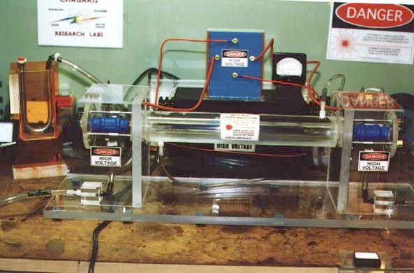
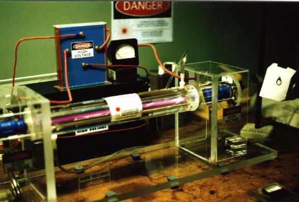
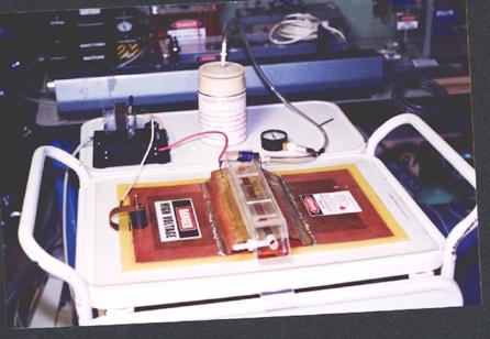
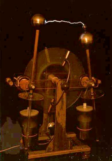
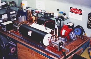
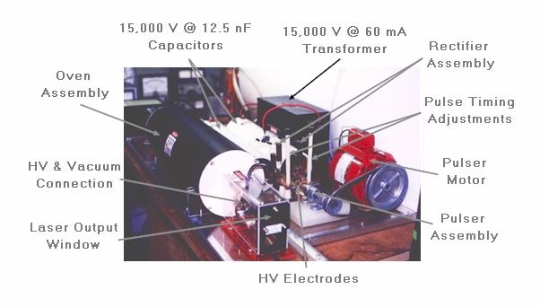
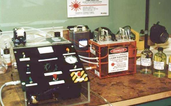
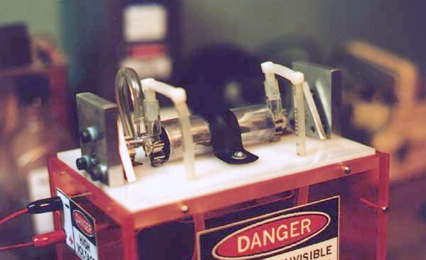