Unfortunately, most of this did not work with Netscape V3.04. Perhaps, it will work with your browser and/or the problems have since been corrected.
For example, the following table shows the expected MTBF hours for a 60X tube as a function of beam current:
   Plasma   -------- Laser Output Power (mW) --------
    Tube     Multi  ------ Gaussian TEM00 Mode ------
   Current   Mode            ------- Pure Line ------
   (Amps)   -- All Lines --   457 nm  488 nm  514 nm   Lifetime (MTBF) Hours
  ---------------------------------------------------------------------------
      4        20      10       1.0      7.0     0.0      15,000 - 25,000
      6        50      30       2.0     17.6     7.5       8,000 - 15,000
      8       110      70       5.0     27.0    23.0       4,000 -  6,000
     10       220     130      10.0     44.0    42.0       1,500 -  2,000
     12       325     200      15.0     60.0    68.0       1,000 -  1,500
     14       430     280      22.0     81.0    98.0         500 -  1,000
Thus, it makes a lot of sense to run at the lowest power that will be adequate
for the application whenever possible to maximize tube life (not to mention
keep your utility bills within reason!).
Aside from obvious physical damage, there are a variety of conditions that can prevent a tube from lasing.
To check, with ONLY the filament powered, look through the mirror at the cathode end of the tube to view the interior:
However, Ar/Kr ion tubes will often have some sort of additional optics at one end, either a line selecting prism or ghost suppression wedge. This will make it impossible to easily adjust alignment at that end at least.
WARNING: Both ends (and possible other parts) of the tube are probably line-connected so these procedures are significantly more dangerous than with a typical HeNe laser. Take care. It may be possible to use the approach outlined in the section: Pulsed Operation of an Ar/Kr Ion Tube for checking alignment at least. However, the mirrors will have been adjusted at the factory when the tube was running at normal operating temperature (hot!) so it won't behave quite the same (this is probably particularly true for longer tubes).
For a detailed description and diagrams, refer to the Cyonics Internal Mirror
Laser Patent.
This tube should do about 5 to 10 mW of 488 blue at 9 A.
It's designed for a 104 volt drop, so you can get it running with just a 7 to
10 ohm adjustable resistor and a bunch of filter caps.
The tube wants to see about 2.8 to 3.0 V for the filament at 15 to 25 A,
magnetron transformers with the HV winding whacked off are a good start.
Adjust for 2.7-3.0 V across the filament after a 30 second warmup. Make sure
it does not exceed 3.2 V after it is running.
Tube current is 9 A maximum, 4.5 minimum. In the past this has corresponded
to a 7 to 10 ohm adjustable fan cooled 700 watt power resistor in series with
the tube after a 20 A bridge, with 2,200 uF in front of the resistor and 2,200
uF behind it in a pi configuration, resistor goes in the positive side.
Cathode connection is via a center tap on the filament winding so the plasma
is evenly balanced.
This will do for a few hours until you can figure out how to do a more
sophisticated PSU, but you will need to watch it like a hawk and have a good
current measuring shunt in series with the tube.
The recommended fan is 225 cfm minimum, a bit less then for a 60X. The
patriot P2B3s are $22.95 from Marlin P. Jones and Associates quantity 1. Make
sure flow is sucking air out of the vee shaped aluminum shroud around the
tube.
Also see the section: Pulsed Operation of an Ar/Kr Ion Tube.
For initial tests, it can be run at a low duty cycle. Power up for say 4 to 5
seconds and power down, just don't rush, unlike HeNe tubes, these do not
stablize instantly.
You want to fire it up and run it, say 1 minute on or so. When all other
causes of failure are accounted for, the igniter pulse becomes the biggest
factor in the life of the tube. It (a) buries gas, (b) blows chunks out of the
cathode until the cathode spot forms and (c) deposits junk on the internal
optics. I'd say don't worry about it, as this one is really overbuilt, it has
the same cathodes and anodes as a 5 watt, and has so much metal that you need
some time to heat it up, unlike a 60X which is critically cooled, this one
will take some punishment, and no amount of energy you can dump into it with a
110 line will rupture or implode or melt it. I have one sitting in the garage
that contained all the fragments when the tungsten disks and cathodes melted,
it held the vacuum as well.
You could run it at 14 amps for short periods of say 1 minute and do no damage
at all, provided you have cooling and the cathode is no higher then 2.8 V Its
when you log hours and hours of operating with a improper supply that you will
damage this, not during short term testing, in fact they are sometimes ran
without cooling to recondition them a little.
It's a good idea to power up and see what is going on then switch off, but it
may take 5 to 7 seconds after ignition for the cathode to come up to final
temp as pressure rises from the discharge heat. Hook a voltmeter across a
current shunt in series with the tube, if it goes way out of range, just
switch off, don't panic, this thing has a much larger thermal mass then a HeNe
tube, and the metal will desorb the pure gas over time, unlike the HeNe glass
which destabilizes the discharge when it heats up enough for ion migration and
the bore conducts/outgasses CO2-N2.
I do my initial checks for 30 to 60 seconds with the lid and fan off, often
taking my time to stick the voltmeter leads across the tube and then the
cathode, and my DVM is slow. Then I simply slide on the fan and cover and run
it at 4 to 5 A for a while or shut down for 5 mins, which is about a 1% duty
cycle. :-)
You will pop a weak ceram to metal seal long before you ever risk a
catastrophic failure. The main safety hazard is reaching in and touching line
side. If it fails the discharge will go out when the cathode opens up.
There is a BeO (beryllium oxide) warning on the tube for those who would
actually grind or smash a tube. Recent discussions with a shop that laser
machines BeO have revealed that the hazard is only for a certain particle
size. They cut it with CO2 lasers every day and set it up so the particles
are outside a certain range without wearing space suits and using only a
simple HEPA filter to recover the BeO dust for remelting as it's an expensive
material with resale value.
An Oudin coil is a sort of hand-held Tesla coil that is adjustable in output
and runs off AC line. It may also be called a Tesla coil or spark coil. A
new one costs about $160 from neon sign equipment suppliers but these are
often found in high school physics labs and other places working with vacuum
systems. You may be able to borrow one for for an afternoon (or longer).
A home-built alternative is also possible. See:
Home-built Substitute for Oudin Coil.
(The Oudin coil is fun as sometimes you get all the energy stored in the PSU
caps to flow through the air in a inch or two spark, pzzzzzap-flash-bang!
Using it around plastic bags of pure noble gasses also is fun. You get 6"
long sparks or glows. The only glitch is if you turn it up too high it can
puncture the brewster stems. The high voltage low current RF field doesn't
damage the PSU or support electronics, even when you see corona off the leads
of solid state component (though I wouldn't press my luck with MOSFETs or CMOS
devices!), yet it will light a nearby fluorescent lamp to the point you can
read by it.)
Plug the coil into the wall and set the knob on the coil for a 2 to 4 cm spark
to metal. Then hold it at the cathode-end of the tube where it can hit the
air riser (metal box below the fan) and the bare ceramic of the tube with the
power supply on (and trying to start). This will totally ionize the whole
tube volume and may allow enough current to flow for the discharge to start.
WARNING: Beware of turning up the spark coil so high you punch holes in the
glass to metal seals on the brewster stems.
If it succeeds, running the laser for a few hours will eventually bury enough
gas that the igniter will handle starting on its own the next time.
This problem results when you don't run the laser for a long time and it
outgasses, I shudder to think how many perfectly good tubes have been thrown
away that just needed a little assist.
A cure for this is to run these lasers at least 30 minutes every three weeks,
like HeNe lasers, they like to run, it takes a couple of months of setting
there for the pressure to really build. On some tubes this doesn't happen
but it is a common problem even with the large frame water-cooled units and is
worse with a krypton fill.
The Krypton red and yellow lines share the same upper state, and what
determines where they fall to ground state is the gas pressure. If your
tube is on the low end, you get a lot of yellow; if it is high you get a lot
of red. Large krypton lasers have a pressure control pump built into the tube.
Two solenoid valves and a gas reservoir form the pump.
Lower tube pressures cause more gas to be buried, leading to a runaway cycle.
An argon tube with clean multiline optics installed that only emits the 488
blue line is a dead giveaway for low pressure and end of life. However,
it could just be dirty optics as the 488 is the highest gain line, it will
lase with a 90% reflector, so try proper cleaning before throwing in the
towel.
(From: Steve Roberts (osteven@akrobiz.com)).
Sometimes for seemingly no reason at all, NEC tubes go south and need a little
starting help. However, first check all the zeners and SCRs on the ignite
board as well as for shorted/leaky caps. Since the NEC laser head generates
its own boost voltage, something may be wrong on the ignite board. Make sure
the filament volts/amps are adequate - cold filaments won't ignite!
If this doesn't turn up anything, just getting some Tesla type HV near the
glass bell may help.
Leaking a spark across to the metal fins on the body may do it as well. Set
the laser on a wood board along with a battery powered Tesla coil. Snake a
single conductor lead over to the laser with the top cover off, then let
the wood act as the return to the HV, if conditions are right, you might
get some faint sparks to the fins to pre-ionize the gas.
As soon as the tube starts, you have about 30 seconds to get the hood on (to
provide cooling), so don't panic. It needs to run to get the pressure down,
DO NOT interrupt the current flow for any reason. (Well, at least not anything
less than life or limb threatening!)
There is a lot more to a Oudin coil then a simple interrupter driven ignition
coil circuit (though this is what it may appear to be from the outside). They
have some unique windings for enhancing resonance and some caps in critical
places. Mine is from the 1930s, insulated by wax. A few years ago I had to
rewax it - paraffin doesn't work, only pure beeswax for some reason (so I had
to rewax it again). I wish I had drawn out the details, but that is a true
resonating Tesla coil in every sense, not just 60 hz pulsed AC.
I've never got a start boost off anything but a pure RF spark, not a sharp
pulse! - hence the confounded wood block setup I suggested.
Oudin coils source so little current they generally do not harm the start
boards, even the UJTs. Its not uncommon to stick one in a laser for 30 to 45
seconds with no harm to the electronics, its extremely high peak voltage,
but NO current, but its broad spectrum RF that seems to contain (and perhaps
adapt) to the natural frequency of whatever its trying to excite, gas wise.
A high voltage high frequency source can be constructed from a TV or monitor
flyback transformer using a transistor or two for drive. Alternatively, an
interrupter (relay/buzzer) or low pulse rate transistor driven circuit using a
flyback or ignition coil can be enhanced with suitable resonant components
(additional capacitors) to promote the generation of RF energy. Note that if
a flyback is used, it must NOT have an internal rectifier as that would simply
result in voltage building up on the stray capacitance of the wiring, tube,
etc., until a discharge took place inside the tube or an arc to something
occurred outside - which isn't what we want.
Some of these home-built devices won't have as great a maximum voltage as the
genuine article but should still be adequate for our purposes. This may
actually be an advantage as there is less likelihood of damaging the tube or
seals with lower voltages.
Where these conditions are met, the most likely explanation is very slight
mirror misalignment.
It would not surprise met that just applying pressure in the right direction to
one of the mirror mounts by slipping a steel tube over it without loosening
the setscrews and it will pop on. It should operate once the mirrors are
somewhat aligned, and even if somewhat misaligned, tubes like the Cyonics
have a curved from mirror and a flat high reflector. This configuration is
set up to tend to correct itself optically from small misalignments.
Mirror alignment can be tested and corrected using techniques similar to those
described for sealed HeNe tubes. See the section:
Checking and Correcting Mirror Alignment of
Internal Mirror Laser Tubes in the chapter:
HeNe Laser Testing, Adjustment, Repair as
well as the section in this chapter for external mirror Ar/Kr ion lasers:
Argon/Krypton Ion Laser Cleaning and Alignment
Techniques.
A spark coil became a permanent resident at his house so he could
somewhat prolong its life, by assisting it in starting. We got the 20,000 hour
figure from a second hour meter buried on the start board. The higher the tube
drop voltage the better, you measure it at the high and low current ranges and
compare against a known good unit.
There is a certain popular laser surplus company, that buys these units, chops
the seal off, fills them with a fresh argon fill at a lower pressure for more
power, doesn't bother to bake them out or replace the cathodes or brewster
windows or drill the bore out so its clear of metal migration. then sells them
for $3,800, after setting the PSU upper limit to 11 amps or so, so you get a
175 milliwatt laser that lasts 3 months and dies from a dirty tube and bad
cathode that was not reprocessed right in order to save time. While I can't
print the name in a FAQ for fear of being sued, I can say: Ask your seller how
your tube was processed. He should say: Oven bake out for under vacuum for 24
hours, flashed the getter assembly, reactivated the cathode, lased it while on
the pumping station or after reprocessing to check it, replaced the brewster
angle windows and possibly the cathode. IF THESE STEPS WERE NOT DONE, think
twice or get a good warranty!
With a complex laser - especially where the resonator mirrors are external
(not inside the sealed tube) - it is extremely important to get the needed
equipment and a manual so you can maintain and clean the laser. The air in
a home environment is not really as dust-free as in a typical lab - and they
still have problems with optics needing cleaning periodically even if not
being used. However, don't overboard cleaning everyday just because you think
the power has decreased - every cleaning is an opportunity to accidentally
scratch the optics - and that will mean permanently lower performance!
Above all, understand the safety implications of a higher power laser of this
type. Furthermore, when first started, an ion laser may operate at or above
its maximum rated power for a short amount of time - regardless of the control
settings. Therefore, additional precautions are a good idea. A set of eye
protection goggles for the range of wavelengths that your laser produces is
highly recommended. Can you place a price on each of your eyeballs?
Cleaning. Not all lens tissue is created equal, and some of it has hard
particles that wouldn't hurt a camera lens, but could spell death to a soft
coating on a laser optic. High grade Kodak tissue in the sealed envelopes is
insisted on by most people in the laser refurb business but they prefer sealed
sterile swabs for all cleaning. You use acetone first and then methanol, and
you never dip the swab or tissue in the bottle, always pour it out so you
don't contaminate the fluid. Always keep a lid on the bottle. If these
fluids pick up water from the air it forms a white film on the optic that
really zaps laser power.
The Coherent Laser Group provides a nice tutorial on Cleaning of Laser Optics.
(Note that this includes a more sophisticated version of the general procedure
described in the section: Major Problems with
Mirror Alignment for sealed internal mirror HeNe laser tubes. However,
the basic principles are similar.)
This technique also works for copper vapor, CO2 and 2 mirror YAG. If you
already have a working argon laser or *green* HeNe laser, you can do red
HeNes. HeNe lasers are aligned at the factory using the 488 or 457 lines of
an argon laser. Hold up an unpowered (red) HeNe tube so a light shines down
its bore and you will usually see a deep blue light transmitted through the
mirrors. This is what we're going to use to our advantage. This technique
was developed the hard way after discovering the techniques described by those
who write laser books are not exactly tested in the lab and often written by
someone who has graduate students to do it for them. The 'Cards with Crosses'
technique only works on lasers that are nearly aligned. The approach described
below works on anything including newly installed tubes that are not yet
centered in their cradles as well as for very short lasers.
My (Steve Roberts) thanks to Dale Harder at H&H Laser Refurb for teaching me
this neat little trick for initial mirror alignment. Dale is the ultimate
prefectionist. His lasers exceed their specs.
It's also the only technique for low gain lasers short of an autocollimator or
factory computerized search mode alignment jig.
This technique works on the fact that the optimized dielectric mirrors used in
laser cavities are often largely transparent or only partially reflective at
wavelengths at least 100 nm away from the design wavelength.
Mirrors within a milliradian of parallel is a hard angle to achieve, and
that's what you are shooting for.
Moral: Once it's aligned and tweaked, don't mess with it!!
THE AUTHOR OF THE FOLLOWING ASSUMES NO RESPONSIBILITY FOR YOUR ACTIONS OR
SAFETY. LASERS ARE FRAGILE, DANGEROUS, EXPENSIVE DEVICES. PROCEED AT OWN
RISK!!!
IF YOU ARE NOT COMFORTABLE WITH ATTEMPTING THIS OR THINK YOU ARE DOING
SOMETHING WRONG, GET SOMEONE TO DO IT FOR YOU, THE GENERAL FEE FOR THIS
AVERAGES $100 to $200 AN HOUR PLUS MATERIALS!!
WARNING: High voltage inside HeNe head.
DANGER: Class III HeNe beams hurt or cause damage if you get it in your eye.
Orange stickers tend to improve the contrast of the reflected HeNe beam, and
they glow when the argon starts to weakly lase, enhancing your chances of
getting it working.
DANGER: Class III and Class IV power levels, use laser safety precautions
appropriate for your laser. When your Argon is lasing, terminate its beam on a
proper beam stop where you can't see the blocked beam. A cumulative exposure
to a medium power reflection can cause eye damage.
DANGER: DO NOT stare at diffuse or specular reflections!!!!
I am assuming you have the output end of the Argon facing the HeNe.
DO NOT clean any optics mount rubber O-rings as these will contaminate the
optic with byproducts after the laser heats up if cleaned with other then
distilled water.
Slowly adjust the optics mount screws so that the weak REFLECTED HeNe beam
from the front coated surface of the Argon HR mirror is visible on the face of
the HeNe, then carefully walk the HeNe beam so it is right back into where it
came from. If this is really good, the HeNe will flicker from you canceling
out lasing with a third mirror, but this is rare. Note that each mirror will
reflect 2 beams, 1 from the front and one from the back of the optic. You want
the one off the coating. Note also the Brewsters may generate more
reflections as well. You will end up with a bunch of dots dancing on the HeNe,
keep track of the one you want. Keep working until you have a stable tight
mirror mount with the beam centered in the hene beam. then back off some slack
to leave room for adjustments of the screws, and recenter the beam. Your
WORKING with FRESNEL reflections, or about 2-3 PERCENT of the HeNe beam, a few
hundred microwatts at best, so turn off the room lights to see the weak beams.
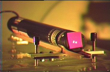
HeNe laser with reflected dot shows the HeNe alignment laser on its 3-point
adjustable mount. The reflections of the HeNe beam from the mirror being
aligned on the argon laser (off of the lower right corner of the photo, not
shown), can be seen on the fluorescent sticker. In this case, the mirror
still needs some more work!
Carefully install the FRONT mirror (nearest the HeNe) after cleaning both
sides using STEPS 1 and 2, above.
Carefully align it using the rear mirror procedure, above.
VERY SLIGHTLY loosen the rear mirror mount, NOT THE MIRROR ITSELF!! and slowly
press it against the Mount holder or REAR PLATE of the laser, rock it back and
forth slightly while doing this, you will see a small flash of laser light on
the HeNe face.
WARNING: THIS PROCEDURE IS FOR LASERS LESS THEN 250 MILLIWATTS ONLY. For
bigger lasers, see the vertical search procedure in the laser manual or use
the fine adjust screws or search bar!!! This flash will tell you which way you
have to move the mirror mount screws, usually opposite of the way you have to
hold or tilt the mirror.
Once you have it steadly lasing, see the sections on Tweaking, Walking the
resonator for maximum power, and Cleaning and general maintenance!!! (some
still under development.)
If you don't get a flash, repeat the alignment procedure until you get it!.
This take patience and time. Commercial laser optics have a small amount of
wedge to avoid creating ghost beams which interfere with the lasing process.
This wedge may be what is messing you up as you may be trying to align the
incorrect reflection!
Instead of dismounting both mirrors, aligning the plasma tube to an HeNe
laser, adjusting the rear (HR) mirror followed by the front one as described
in the procedure starting with the section: Argon/Krypton Ion Laser Cleaning
and Alignment Techniques, I took off only the HR. After that, I put my HeNe
in from the rear and aligned it so that the dot was centered coming out of the
front mirror.
Then I used the procedure from the section: Aligning the Rear Mirror but
first on the front mirror, followed by the HR, which I aligned very carefully
till the lasing began. I then adjusted both the front mirror and HR for
maximum power.
I found this to be an easier way especially because the front mirror was not
that easy to remove (the photodiode light sensor is on it) and the adjusting
of the argon and HeNe was a bit easier (the bore for the outgoing laser beam
is much smaller than the end of the plasma tube, so it was easier to get the
HeNe beam in the middle). Now at least I had only to remove one mirror. The
mirrors are hygroscopic (they love water), so it is not good to remove them
for a longer period than absolutely necessary.
Theoretically, an argon laser should produce 5 wavelengths: Two greens, two
blues and a violet. Try passing the beam through a diffraction grating or a
prism to observe if all these lines [colours] are present.
If you laser is 'out of tune', the violet line will be the first to disappear
so you could try adjusting the resonator screws ONE AT A TIME (and without
adjusting the apex screw/nut) to see if you get more/less violet.
DISCLAIMER: If this causes any problems/damage or reduced output - don't
come crying to me
This only works with medium and large frame lasers that have snap in optics in
bayonet mounts that maintain alignment, air-cooled lasers with mirrors held by
a clamp and "O" ring can't use this because they don't have repeatability in
the optics mount, although if the laser is peaked you can take one mirror at a
time out and it has a 90% probability of coming back lasing at least weakly,
though its position will need to be adjusted.
Looking at the laser you should see something like this:
DO only BOTH verticals then do BOTH horizontals. Then do BOTH verticals
again!!!!!!! (repeat the sequence).
If you start playing with adjustments like "OK, I'll do the front vertical
then the rear horizontal then the rear vertical then the front vertical again"
you are not moving the axis of the lasing cavity relative to the tube, you
are just misaligning your mirrors at random.
Now it is not uncommon to just have to slightly touch just one vertical or
horizontal adjustment on the laser from time to time, for a small fraction
of a turn to get around a power loss from drift in the mounts or from
vibration, slippage, settling in the mount springs etc. Because the
brewster windows are oriented vertically, they tend to act as a non
dispersing (not splitting light into its spectra, meaning beam bending)
prisms inside the cavity, which means most often a vertical adjustment will
be what is needed, in fact most large lasers have a knob or other means for
rapidly scanning the vertical adjustment to find to reestablish lasing if
its lost, cause the vertical alingment of the mirrors is the harder then
horizontal.
So most of the time all an air-cooled laser needs is a touchup on the rear
vertical mirror. If there is an intracavity (line selecting) prism, that
complicates things so you might try the front vertical screw for maximum,
once you get the feel, do the horizontals. It has to be learned by practice.
Your eyeball is not a good laser power meter, there are usually jacks provided
on the laser head to hook to a analog voltmeter, or in the case of the Spectra
Physics or NEC lasers, the front panel meter on the power supply, to see
when the >output is peaking. If you don't have a meter, the trick is to use a
diffraction grating or prism to get the spectrum of the laser on the wall
(assuming you have a multiline laser) and peak the lowest gain lines lasing,
which are the deep blues and violets, since they have so little gain, you
can see their intensity go up and down due to small movements of the mirrors.
Another trick is when the laser is in constant light mode, to monitor the tube
current, as the cavity is peaked, the current will go down.
(Pulling out my manual) The power control is a 50 ohm linear pot, going
to points N, O, and P on the circuit board (N is the wiper, O is the ccw
extreme, and P is the cw extreme)
My 162A has an "older style" rectangular connector that has flat pins oriented
either horizontally or vertically to provide polarization. Sorry I don't know
the brand, but it's definitely not an AMP twist lock. The manual shows the
type of connector I see on mine, so you must have an OEM version.
I adjusted the mirrors. I am now getting about 22 mW (so says the meter on
the front) of the blue/green line. It just needed some adjustment of the
vertical adjustments (It just has allen screws. One thing though, If I move
the rear vertical adjustment I get the other lines. I guess it is a beam
selecting prism. I called SP today and they are looking up the info on the
multiline optics. Since I can tune the laser to the desired line, does this
mean I will only need to get a different high reflector and not a different
output coupler?
What I am thinking is that the guy that had it before me (who knew next to
nothing about lasers or electronics) played with the pots and variable
capacitors on the control board. Does anyone know the procedure to reset
these settings to normal?"
There is some calibration and alignment info in the manual.....
Depends on the cooling fan on top. The small fan units are limited to 9 A,
the large fan unit is limited to 12 A.
The manual does list part #s for the optics, but considering it is a 17 year
old laser, the parts are probably discontinued by now.....
The manual is not real clear on this, but from my experience, about 25 mW (all
lines) seems about right. That .12 W (120 mW) seems high.
Good deal - I paid $90 for a head, and had to build my own supply! Got any
more???
P.S. Watch your eyes - 25 mW of argon laser light can do damage quickly.
Also, watch out around that power supply, 140 V at 10 A can kill!
(From: Frank Roberts (Frank_Roberts@klru.pbs.org)).
I have come across a Britt medical argon laser which appears to be a pulsed
design. It is about 1 meter in length, runs off 240V single-phase AC and is
air-cooled. The power supply is integral to the laser head itself, and
appears to be a flashlamp type design. What I mean here is that the 240 VAC
is rectified to about 340VDC and applied directly across the tube and a
considerable capacitor bank for energy storage. The laser is fired with a
high voltage trigger pulse applied to a trigger electrode wrapped around the
tube bore itself. All the electronics appear to be functional in that indeed
the potential measured from anode to cathode is about 340 volts DC. A string
of 3 100W lamps burns brightly across the supply, so it is sourcing current as
well as voltage. The cathode filament does light up as expected and a high
voltage pulse of several hundred PPS is applied to the trigger electrode.
This pulse easily jumps an air gap of about 1/4", so I assume it's healthy
also. Only one problem, no discharge. I applied a 7.5 KV neon sign
transformer across the tube to check tube integrity and the tube did light up
with a characteristic argon color. I know the difference between nitrogen
purple and argon lavender, and the discharge color was indeed the color of
argon. One added note: The getter deposit inside the tube is shiny, indicating
no air leaking into the envelope.
There is a gas recharge system built into this laser and the vacuum gage on it
seems to indicate an overpressure condition. This may be the only thing
keeping this laser from firing. Methinks that somebody got a little
punch-happy with the recharge button. Each time it's pressed, a tiny amount
of fresh argon is metered into the tube.
I'm sorry to be so wordy, but I'm trying to come to some kind of decision as
to what to do with this laser, and would appreciate some input from my fellow
laserists out there. I do not have a vacuum system readily available to me at
this time. I do have a three-stage pump capable of pulling a vacuum of 6
microns. The decal on the tube indicates the operating pressure of the laser
to be 40 microns. It's theoretically possible to pump the tube down below
it's operating pressure and then refill the tube from the recharge supply.
(From: Steve Roberts (osteven@akrobiz.com)).
You'd need a 10E-8 Torr vacuum or better.
Attempting to repump a ion laser with getters without rebuilding the tube is a
no-no. The getters will powder and end up in the bore, destabilizing even
pulsed lasing, then it will find its way to the most electrically neutral spot
in the tube, the brewster windows via Murphy's law, thus suppressing or
killing lasing. You really need a turbo pump to clean the water vapor out of
the tube, else lifetime is nil and the cathode will be shot. The Britt is
pulsed but it has a 2-3 mW quasi cw simmer mode for aiming for 15 seconds at a
time. The pressure in a pulsed argon is much much lower then the similar
sized CW argon which would have a pressure of around a torr and needs a much
cleaner gas fill.
Hint, hint: Might I suggest building a styrofoam reservoir around the gas
bottle and ever so slowly chill it down with LN2, then pulse the solenoid till
the pressure goes down using Mr. Boyles and Mr. Charles's laws for gases in a
constant volume enclosure. You are not trying to freeze the argon, only to do
sorption pumping onto the glass and volume reduction per basic
physics. Otherwise you'd have to do a thorough the reservoir repump, as soon
as you cracked the seal on the tube you'd suck in enough dirt from the
atmosphere to fog the windows big time even in a clean room.
Note I'm leaving out details of how you'd have to go about reprocessing a
cathode if it ever sees nearly atmospheric pressure in argon etc because I
work closely with a refurb shop and can't give away all the secrets etc. I
will say the LN2 trick works however.
(From: Frank Roberts (Frank_Roberts@klru.pbs.org)).
My god Steve, the LN2 idea's so simple I'm ashamed that I didn't think of
that. A neat little variation on the cryo pump. According to Merck, Argon's
normal boiling point is 87.28 K while LN2 boils at 77.36 K. LN2 should cause
the argon in the reservoir to sweat the inside of the metal tank. (Now to
calculate the vapor pressure of liquid argon at 77.36 K.) To add insult to
injury, I was a physics major the first time around. I should have caught that
one, thanks for the tip. I'll let you know if it works.
(From: Dean Glassburn (nitelite@concentric.net)).
Actually the Britt laser comes with a cryo attached to the tube on the end of
the copper pipe. pull it away from the tube while the head is suspended upside
down and place the cryo into a cup of LN. wait until the copper tube frosts
up, about 10 minutes, then open the large valve connected to the assembly,
about 1 turn. This will pull the tube below the operating range. on the end
of the laser put the switch into the standby range and turn on the
system. this will outgas the cathode. remember to keep the cup filled with
LN. if you have a gauge it should be reading zero. Shut the valve, remove
the LN, and allow the temp of the cryo to come up to room temp. At that point
you can turn on the system, add gas back to the tube using the refill button
until about 25 milliTorr is there. You should get the tube to ignite. Keep and
eye on the pressure as it will use gas very quickly initially. Once
stabilized, you can fire off the getter using a 12 volt transformer and a
variac to heat up one of the getter filaments to a dull orange. Do this only
if the gas has a pinkish discharge around the cathode neck and anode.
(From: Steve Roberts (osteven@akrobiz.com)).
I have only once seen a Britt on a trip to a conference in Canada, now I know
why they last so long. A built-in pump, a built-in fill system, and a built-in
cleanup system, and not to mention some of the most beautiful glasswork ever
done. Too bad these features don't come on CW systems. :-)
Cyonics Tube, Testing, Hard-to-Start Tubes, Problems
Cyonics Argon Ion Tube
This is typical of a well-built small sealed internal mirror argon ion tube.
Cyonics is a Division of Uniphase
Corporation, 408-434-1800.
Testing a Small Ar/Kr Ion Tube
This was written for the Cyonics but portions apply to others like the tube
used in the ALC 60X or Omnichrome 532.
Hard-to-Start Ar/Kr Ion Tubes - Outgassing and Keeping Your Laser Healthy
If you don't run them periodically, gas is released from the tube walls and
then it can build to such a level that the tube won't start, so you have to
spark them in the right place with an Oudin coil of the neon sign shop/vacuum
lab variety till they start and bake them at full current for a few hours to
drive the pressure down by burying gas into the metal parts of the tube. This
is easy when you have a plasma core that is hotter then the surface of the sun
and has 170 nm extreme ultraviolet photons bouncing around from every ionized
atom in the tube!
Problems with NEC Argon Ion Tubes
The comments below were prompted when the NEC-3030 tube in the laser head Ben
was using with his version of the home-built SG-IL1 power supply described in
the section: Ben's Linear Ar/Kr Laser Power
Supply (BJ/SG-IL1) refused to start for no apparent reason.
More on Oudin Coils
(From: Steve Roberts (osteven@akrobiz.com)).
Home-built Substitute for Oudin Coil
Oudin coils or hand-held Tesla coils aren't the sort of thing to turn up at
your typical garage sale (although you might find one at a high-tech flea
market or hamfest). However, it should be possible to construct something
suitable for dealing with hard-to-start Ar/Kr ion tubes at minimal cost.
The typical hand-held Oudin coil (may also be called a Tesla coil or spark
coil) from external appearances would seem to be just a line powered high
voltage transformer driven like an ignition coil with a buzzer type of primary
interrupter. However, from the section: More
on Oudin Coils this is not the case (at least for some types) and produces
significant radio frequency (RF) energy - not just a stream of pulses at 60 or
120 Hz.
What Could Prevent an Internal Mirror Tube from Lasing?
If it has good pure argon at the right gas pressure, a working fan, the proper
stable current down the bore and reasonably aligned clean mirrors it will
lase. The 488 nm line will lase from .01 torr to 2-4 torr even with dirty
mirrors, so it's almost guarenteed that you will get something. I doubt
there is dirt or scratches in the optics as those would not leave the factory.
Tips for Potential Ar/Kr Ion Lasers Enthusiasts
Caveat Emptor
A local 17 year old paid $700 for a NEC 3030 with 20,000 hours on it, it was
missing the hour meter when he got it, it was rated for 40 mW and doing 10
when he got it, it took all of two months of intermittent use for it to die,
and that was half a summers's spare wages for him, that could have been
avoided by putting a voltmeter across the tube and measuring its drop, which
is a function of pressure etc. WARNING: Lethal voltages and currents around
the tube.
Hands-On is Best
Actually having access to one of these small ion lasers is definitely the best
way to learn but keep in mind that what you will likely get your hands ON is a
20 year old design so you need to stock a few things (assuming a laser with an
external mirror tube) like gas chromatograph grade (or better) acetone and
methanol for cleaning the 5 active optical surfaces. Swabs in individual
sterile packages with wood sticks are generally best for Optics.
Argon Laser Anonymous
A big warning here is these are addictive, suddenly you find yourself trying
holograms and illuminating low clouds and looking at the ramen scattering
spectra of beer.
Argon/Krypton Ion Laser Cleaning and alignment Techniques
Lasers for Which These Procedures Apply
The following was developed for a typical 100 mW external mirror argon laser
(henceforth referred to as 'Argon'). It will, of course, also be suitable for
a krypton ion or mixed gas laser.
Chemicals and Supplies
These assume hard coated dielectric mirrors for HeNe or ion lasers. (Those of
you with CO2 and excimer lasers with salt optics or group III-IV semiconductor
optics will will need other materials, consult your laser supplier or optics
manufacturer for details.)
Required Equipment
Alcohol or acetone sold over the counter in the United States will contain
denaturing agents or tracking chemicals to prevent unintended uses such as
drug making. These show up as a white film on the optics. Get these chemicals
from a lab supplier who can attest to the purity. (Kodak or Omnisolve is
preferred). Keep the lids on the bottles so as not to pick up moisture from
the air, and always pour out what you will need into a smaller container to
avoid back contamination of your primary source from swabs or lens tissue. I
flow warm filtered argon gas into my bottles before resealing. This aids in
shelf life of these expensive fluids. DO NOT attempt to use common isopropyl
(rubbing) alcohol for optics cleaning as it will leave a thin polymer film on
your optic that is hard to see but really decreases lasing power. You can
tell if you have water in your fluids as they will 'ball up' into droplets
that hang around after the film of cleaning fluid evaporates.
The Alignment Jig
I can't afford optical benches on my budget. I needed a long bench to work on
my lasers. The solution was to go to the local aluminum company and see what
they had in the computer as leftovers from a larger sheet that was cut to
order for a customer. A 1/4" thick 3.5 foot long 14" wide piece of T6061
polished on one side was $40. A 16 foot piece of 1" x 1" finished square
stock was 25 dollars.
[]___________[]
If you do it right, this will turn out to be very strong and stiff, as well
as flat from end-to-end and side-to-side.
Initial Bore Alignment
Watch out for stray beams that come off the Brewster windows!!!!!
You are now ready to deal with the Argon:
Optics Cleaning Procedure
These two steps will be repeated for each optic surface:
Now repeat the same procedure on the high reflector mirror until clean and
let dry. Clean the back side of the optic as well as the face, as contaminants
migrate.
Aligning the Rear Mirror
Install the high reflector (HR, rear mirror) into the far end of the Argon
making sure the coatings face inward.
Aligning the Front Mirror
Clean the FRONT Brewster Window using STEPS 1 and 2, above.
Powering up the Argon - Final Alignment
Making sure you have proper cooling for the argon laser, leave the HeNe on and
switch the Argon ON and turn the tube current up to the upper limit, then back
it off a little. This should be About 9 amps if you have a 10 Amp maximum
laser. Let the laser warm up. DO NOT EXPECT IT TO LASE AT THIS POINT. If it
does laser you are very lucky or you have a large frame (e.g., 1 meter long)
laser.
Additional Alignment Information
Markus's Comments on Argon Laser Alignment
(From: Markus Hakes (mah@josquin.pc.rwth-aachen.de)).
Multi-Line Tuning
(From: L. Michael Roberts (NewsMail@laserfx.com)).
Disks for Laser Alignment
A Spectra-Physics tech just showed my friend at Sea World a neat trick. He
had round disks with rims that slip over the optics without touching the face
of the mirrors. Each disk has holes that are centered in the face of the
mirror. You peak the laser with a disk with a large hole and keep switching
to disk pairs that have smaller and smaller holes until the beams are centered
on the mirrors, which results in maximum beam quality and power.
More on Mirror Adjustments
Moving any adjustment more then 1/2 turn will probably kill lasing unless you
have the nice scientific unit with the 80 pitch adjustment screws, so be
extremely careful to remember what you just did, it doesn't hurt to take a
pencil and mark a mark on the knob/nut so you can see where it was before you
started adjusting. Bigger lasers have dial turn counters installed so you can
see where your at. One of the tricks is to push on an end plate with a finger
to see if the beam gets brighter or dimmer - you are changing the mirror's
angle by a milliradian or so, and it makes a difference. This is a good quick
check to see if something is messed up. If the setting is just slightly off,
a small touchup on the adjustments should send the output power way up. It
won't need much - just a fraction of a turn, as you move the screw back and
forth. Power should peak and then go down again - that is the time to stop
and go the other way, loss of alignment is a real pain to correct!!!!
       @ Vertical adjust
       |
       |
       |
       |
       X---------------------@ Horizontal adjust
     pivot
The pivot is never touched once the laser mirrors are being walked for best
cavity alignment relative to the tube bore during initial alignment. Then, all
the user ever has to do is slight touchups on the vertical and horizontal, a
rule being:
Spectra-Physics Argon Ion Laser (SP-162) - Discussion
(All replies from: Frank Tompkins (frank@Uakron.edu)).
Britt Pulsed Argon Ion Laser - Description and Gas Adjustment