K3PGP.Experimenter's.Corner
![]()
K3PGP.Experimenter's.Corner
![]()
Home Astronomy Construction Laser Moonbounce Software Guest Misc
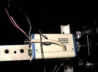
Mintron
Mods - Adding external switches (Remote Control) to the Mintron
12V1E-EX camera
WARNING:
Making any modifications to your equipment will VOID THE
WARRANTY. You do so at your own risk.
NOTE: Work in progress !!! - For a smaller remote control which will also work with this camera see the DX-8263SL color camera remote control.
 |
 |
|
 |
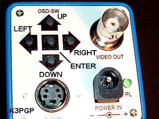
U=UP D=DOWN L=LEFT R=RIGHT E=ENTER G=CHASSIS GROUND
NOTE: Do NOT hook external wiring directly to any circuitry inside the camera. Doing so will make the camera sensitive to static discharge and you most likely will end up with a VERY expensive repair bill or perhaps something that is not worth repairing. The remote control described here uses opto couplers to isolate the internal circuitry from the outside world.
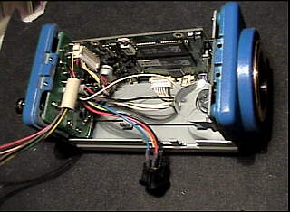
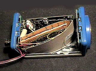
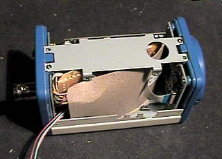
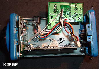
In my camera it looks as though the main circuit board and CCD circuit board were machine assembled. However the rear circuit board that the switches are mounted on looks like it was hand assembled. Considering the small size of this camera, the easiest place to connect to appears to be the back side of the circuit board that the switches are mounted on. See lower right photo and schematic above.
Opto couplers are used to isolate the external wiring from the internal cicuitry of the Mintron camera. This prevents static discharge from damaging the camera. Although most any opto coupler should work, I used the 4N32 because I just happened to have quite a few on hand. The 4N32 opto coupler provides ~2500 volt isolation. Since I am running 50 to 150 feet of control cable between the telescope and the house this IS important especially when the humidity is low and static discharge is common!
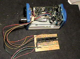
I made use of a dual polarity control system to reduce the number of conductors to four. This makes it possible to use the S-VHS connector on the back of the camera or the remote lens connector on the side of the camera as a connector for the remote control system provided of course that you are not using these connectors for their intended purpose. In the prototype I simply slid the remote lens connector out of it's slot and ran the four control wires through the remaining hole. I intend to redo this and use the S-VHS connector on the rear of the camera for my remote control connector. The S-VHS style connector is available at Radio Shack and most video supply houses although you may have to purchase a cable and cut it in half to get a connector! The opto couplers could be interfaced to a computer (printer port?) if needed.
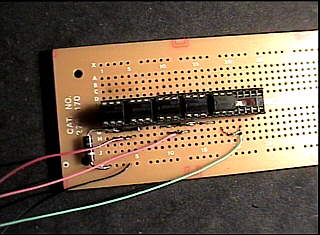
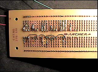
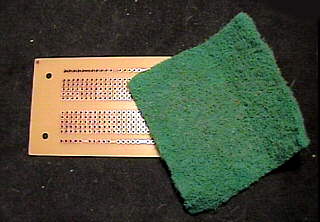
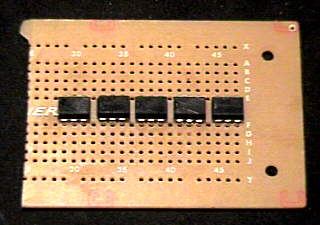
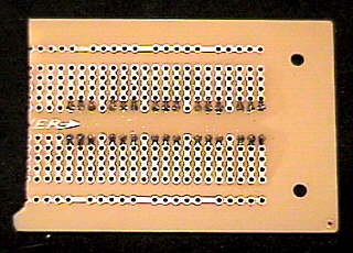
For those of you that can't wait, here are preliminary schematics of the Mintron Remote Control Interface. These are PRELIMININARY schematics and have NOT been checked for errors!!! The photos below are of an oversize prototype which was thrown together in a couple of hours reusing parts and circuit board from another project which is why the pc board looks so messy. This proves it doesn't have to look nice to work! As long as you are careful about what you connect on the camera side of the interface you should not have any difficulty. The remote control side of the interface is completely isolated from the camera!!! Voltage is not critical. Anything in the +/- 6 to 12 vdc range will work. . . . . . . . |
|
Please keep in mind this is a PROTOTYPE and I didn't want to spend a lot of time on it trying to make it look neat.
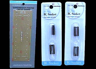 Parts you will need are available at Radio Shack. You might want to consider using an 18 pin socket (or NO sockets if you are brave) as this will allow three opto couplers per socket and will result in a smaller interface. The remaining two can go in a 14 pin socket. |
|
|
|
|
|
|
|
If you do not need the 4 pin S-VHS connection on the back of the camera you should be able to reuse this connector for the remote control as this connector provides four connections. Same with the remote lens connector on the side of the camera although a 4 pin S-VHS connector is available at Radio Shack. My next step is to build a neater and smaller PCB that fits better inside the camera and use the 4 pin S-VHS connector for the remote control.
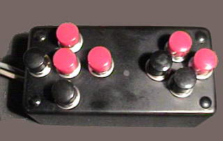
9 volt batteries were used so the system could be used in the field. Since the current drain is extremely low and only used when a button is pushed battery life should approach shelf life. The two 470 ohm resistors in series with the batteries are needed to prevent a short circuit should both the up / down or left / right switches be pressed simultaneously! The resistors limit the current to a safe value.
|
|
|
|
Home Astronomy Construction Laser Moonbounce Software Guest Misc
Contents of this website are ©1997-2014 of K3PGP anr> the originating authors.