K3PGP.Experimenter's.Corner
![]()
K3PGP.Experimenter's.Corner
![]()
Home Astronomy Bicycle Construction Laser Moonbounce Software Guest Misc
Ultraviolet
Infrared (700 nm) blocking filters
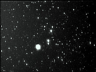
If your CCD images have been plagued by '-fuzzy focus-' or halo effects that should not be there then you may need to invest in an IR blocking filter. Many otherwise excellent refractors have a very serious flaw when it comes to CCD imaging. Sure, we've all seen violet fringes from time to time when looking through the eyepiece. CCD imaging devices don't notice this until the problem gets to be severe as the response tends to droop at the blue / violet end of the spectrum. But what happens at the other end of the spectrum (red / infrared) where the response of most CCD imaging devices is better than human vision? If the refractor does not focus deep red / infrared to the same focal point as the rest of the light spectrum the result is the following (left photo):
|
|
|
| Those of you with decent star maps, check out the magnitude of some of the dimmer stars visible in the right photo. Focus is EVERYTHING when it comes to being able to image dim objects! And this is from a very light polluted area. On most evenings the sky in my backyard is lit up to the point where I am lucky if I can see 2nd magnitude stars naked eye. I don't think I can see any of the stars in any of these photos naked eye from my location and most are not visible in a small scope due to light pollution. The center photo is the first photo taken with the IR filter installed on the 16-160 mm zoom lens running at 160 mm and is the first time I ever saw a starfield like this through this system. The focus was further refined and the camera tilt corrected a few days later when the weather was a bit better. Although it took me over a year to get back to updating this page the final result is visible in the right photo. The most interesting aspect of this is the filter DOES introduce some loss into the light path although very slight. Yet even with that additional loss dimmer objects are visible due to the better focus. Before the filter was installed the photo at left was the best focus than could be achieved. When the focus was moved in one direction the infrared energy would be going out of focus as the visible light was coming into focus. Going the other direction the infrared light would be coming into focus as the visible light was going out of focus. At no point could sharply defined images be obtained. The photo at left was the best compromise. The slight grain in the background of the center photo is being caused by moonlight and light pollution being scattered by a thin cloud layer. There was no moonlight when the right photo was taken. |
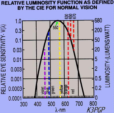
Note the fuzzy images and the severe halo effect around one of the stars. This particular object radiates very strongly in the deep red / infrared part of the spectrum. After adding an IR blocking filter (the one I have also blocks UV!) the photo in the center and on the right is the result, the object being to pass as much of the light spectrum as possible while blocking the out of focus infrared energy. In particular the system should pass wavelengths as least up to 656 nm but NOT pass wavelengths much higher than 700 nm or so. (Hydrogen lines are at 410, 434, 486, and 656 nm.) In the case of this filter the passband is quite flat up to 700 nm then the loss increases dramatically. It's extremely unlikely that you will notice if your telescope has this problem simply by looking through the eyepiece as the human eye has very poor response even in the near infrared (wavelengths around and slightly longer than 700 nm). The filter makes the CCD camera response more like the human eye. Tests of a $25 700 nm UV / IR Blocking Hot Mirror Filter follow.
|
|
Hot mirrors are the preferred type of IR blocking filter due to their low loss in the visible spectrum and very sharp cutoff below 700 nm compared to the cheaper blue - green glass type of filter which is typical in most color CCD cameras. The blue - green glass type of filter is part of the color correction neccessary for some types of camaras but unfortunately can have high attentuation throughout the visible light spectrum with only a very gradual IR cutoff making it less desirable for low light astronomy imaging. I also have one of these type of filters and hope to provide a comparision between it and the dielectric type hot mirror blocking filter sometime soon. I NEVER use the blue - green glass type filter for low light applications due to it's high loss and poorly defined cutoff wavelength.
NOTE: If you are using a reflector and have no glass lens in the light path you most likely do NOT have this problem as most reflectors should have no difficulty focusing the entire light spectrum to a single point. This discussion applies mostly to refractors or those systems with any type of lens in the light path that do not focus the UV or IR end of the spectrum to the same point as the other parts of the light spectrum. This does not mean that you can not use your CCD camera for infrared astrophotography. What it means is you can not use a CCD image sensor to image visible light and the UV or IR end of the spectrum simultaneously with SOME types of optics. There is absolutely nothing to prevent one from using the exact opposite type of filter (known as a cold mirror) to block the visible part of the light spectrum and pass the infrared part of the spectrum below 700 nm.
GMV-EX6K / MINTRON
12V1E-EX CAMERA
Light source attenuated - Camera in 128x (2 second) integration
mode.
Dark frame subtracted! These are VERY dim objects in the
following tests.
PC-164C Tests, photos of test setup,details of the filter and
more info to follow.
A good UV-IR
blocking filter should pass red, blue and green light with little
attenuation
but severely attenuate UV and infrared.
Light Source |
No
Filter - 100 frames |
UV-IR
Blocking Filter - 100 frames |
|
 |
 |
|
 |
 |
|
 |
 |
|
 |
 |
Light source is System required |
|
|
|
Testing |
Testing |
NOTE: The white LED light source was replaced with an incandescent light source and IR filter rather than an infrared LED as I wanted a broadband light source (700 nm and longer wavelengths) for the infrared tests. The high power of this source proved beneficial in that the intensity could be increased to the point where some infrared light got through the UV-IR blocking filter. When the blocking filter was removed from the camera the system was almost saturated from the intense infrared source proving just how effective the filter is in blocking infrared. I was amazed at how little attenuation this filter had in the visible part of the light spectrum. The background grain in the white, blue, green and red photos is about the same with or without the filter indicating the signal to noise ratio was almost identical.
- Results using REAL stars -
|
|
|
|
I had to rotate the camera slightly to get the system back into focus after inserting the UV-IR blocking filter. It's still slightly out of focus but this was the best I could do as the temperature was close to -17 degree C! The camera was in 2x zoom mode for the middle and right photos. The UV-IR blocking filter photo (right) was taken near full moon with light clouds rolling by on 01-07-03 ~11:30 PM EST. I had to rotate the camera to get the system back in focus and didn't bother to correct the rotation as it was near -20 degrees C and windy by the time I got the filter installed. A more recent photo taken on 11-15-04 is also shown after the focus was refined and everything tweaked for optimum performance. I have no idea of the magnitude of some of the dimmer stars as I can't find them on my star chart.
Infrared Star Info
| HD 11979 SAO 37673 BD+44 398 Visual Magnitude: 7.56 Color Index: 1.18 Spectral Class: Mb Annual Proper Motion: 0.039 0.001 J2000 RA: 1h 58m 44.33s DEC:+45 26 06.9 Date RA: 1h 59m 02.69s DEC:+45 27 32. |
 |
Animation showing difference in scope performance
with the UV-IR blocking filter. Noise caused by moonlight on thin clouds. This was not a good night for tests like this but I was anxious to get some idea as to how the filter would perform in actual use. See the photo above taken on 01-15-04 for the final result. |
|
|
The center star in the left photo of M45 is now resolved into four stars in the right photo! The right photo was taken near full moon making some of the dimmer stars less visible.
NOTE: I found out later the camera gamma was set to 0.45 for the left photo and 1.0 for the right which makes the right image have more contrast and appear darker. The camera was in 2x zoom mode when the right photo was taken, a mode I very seldom used up till now because stars appeared as fuzz balls without the UV-IR blocking filter.
Pictures of the scope used to take these photos.
01-26-04 - Some new info just discovered
|
|
If the charts above are correct, a lower loss system can be built by using a cold mirror, something I will be investigating in future tests. If this is true then dimmer objects can be imaged by using a cold mirror instead of a hot mirror as an infrared blocking filter. However, the RGB / IR loss tests that I've run on the system indicate that the insertion loss of the hot mirror is almost undetectable in the visible range so I have to assume the above normal incidence chart is either in error or a worst case measurement.
 |
Here's what happens when you tilt a
hot mirror |
Home Astronomy Bicycle Construction Laser Moonbounce Software Guest Misc
Contents of this website are ©1995-2012 of K3PGP and of the originating authors.