K3PGP.Experimenter's.Corner
![]()
K3PGP.Experimenter's.Corner
![]()
Home Astronomy Bicycle Construction Laser Moonbounce Software Guest Misc
A 432 Mhz receiver front end protection device
as it appeared in the April 1977 issue of 432 EME NEWS by K2UYH
- Thank you I8CVS for the photocopy -
This filter has been successfully
duplicated on 144, 220, 903 and 1296 Mhz with very similar
results!
The 144 Mhz model was shortened to 12 inches to make the filter a
bit smaller and used more C in the middle to tune the filter to
144 Mhz.
The 1296 filter was 2 inches long and used the same tuning
capacitor. It was found out many years later that the 1296 filter
could be tuned to 903 Mhz where it was just as effective.
Since search engines are unable to read graphics, here is the text from the above photocopy:
From the April 1977 432 EME NEWS by K2UYH
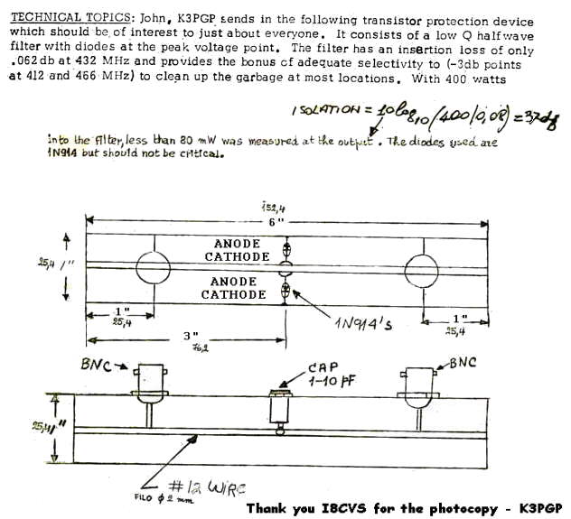
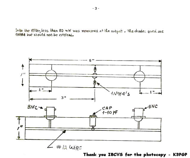
TECHNICAL TOPICS: John, K3PGP sends in the following transistor protection device which should be of interest to just about everyone. It consists of a low Q half wave filter with diodes at the peak voltage point. The filter has an insertion loss of only 0.062 db at 432 Mhz and provides the bonus of adequate selectivity to (-3 db points at 412 and 466 Mhz) to clean up the garbage at most locations. With 400 watts into the filter, less than 80 mw was measured at the output. The diodes used are 1N914 but should not be critical.
I still have the original filters and will include photos soon. The first one (432 Mhz) was built right after I blew out the expensive transistor in my latest 432 Mhz preamp due to a T/R relay problem. All filters were constructed out of single side copper clad PC board (copper side in - where the diodes and tuning capacitor are mounted).
I have never tested this filter with any diodes other than 1N914. Although it is quite likely that most any diode would work, I have no idea what may happen to some less rugged diodes when presented with a severe overload like a 400 watt transmitter connected directly to the input of the filter, something which I KNOW this filter can handle as that is precisely the way I tested it!
I'll never forget the brute force overload test when I dumped 400 watts directly into this filter. After about 20 seconds the RG-8/U jumper between the final amplifier and the filter EXPLODED spraying hot polyethene all over the shack. Fortunately I was not in the path or I would have been severly burned as it was smoking hot as it left the coax under high pressure and flew through the air! The filter nor anything after the filter was damaged. Fortunately I had the amplifier running at 400 watts and not full power or it may have been damaged as well! I know many hams know precisely what a burning transformer smells like. But not everyone knows what burning coax smells like. Other than maybe the early moonbounce experimenters that didn't have access to the types of coax we have today and did foolish things in the interest of learning something like I did with this filter. But it did prove a point under actual worst case conditions so indeed something was learned! Back then replacing an RG-8/U jumper cable was a LOT cheaper than replacing a low noise front end transistor. And the high power tube RF amplifiers were obviously rather rugged beasts especially when the power was backed off like for this test.
Keep in mind the diodes will start to conduct at weaker than expected signal levels as they are connected at the voltage maximum point of the tuned line which will cause the insertion loss to go up. If you are interested in making accurate insertion loss tests you MUST keep the signal levels LOW! Do NOT change the tap point in an effort to achieve a better match. The insertion loss is already about as low as you are going to get and due to the reciprocal nature of the filter, the output impedance of the filter will be pretty much the same as whatever you connect the filter to. Changing the tap point may reduce the effectiveness of the diode limiter resulting in more power feedthrough during an overload. Exactly when you need all the isolation you can get!
In some cases of extremely high impulse (line and ignition) noise I have actually seen the diodes start to conduct and reduce the impulse noise. In order to enhance and further investigate I did some experimentation using one of these filters in front of a preamp followed by another one on the output of the preamp. Inserting the output filter completely eliminated a power line noise problem I had on the terrestrial antenna! It was MUCH more effective in eliminating the noise than the noiseblanker in the receiver due to the much wider bandwidth.
I have never had any problem with the filter generating intermod or crossmod but I suppose that could happen. The only thing I have seen is the loss of signals when a very close by transmitter (on the SAME BAND) comes on the air which causes the diodes to conduct. But this is precisely what this device is supposed to do! Although it was designed for weak signal 432 Mhz work it also worked very well for Oscar satellite work where I was transmitting on 144 and listening on 432 or transmitting on 432 and listening on 144 where I used an identical filter scaled to 144 Mhz.
I have NEVER lost a recever front end when using this device.
Using the filter / protection device as a TR switch !
For the past couple of years I have been using this filter as a TR switch on an experimental 10 mb/s 100 watt 915 Mhz data link. The transmitter is connected to the antenna using an 890 Mhz cell phone circulator. The third port is connected to the filter / protection device which then feeds the 915 Mhz preamp. There are no moving parts nor bias required to go from Tx to Rx and as a result no delay when going from Rx to Tx and back! This also makes the system failsafe as there are no bias voltages that must be present for the system to switch properly. Before I came up with the circulator I used 1/4 wave lines for isolation.
A similar arrangement was used on a 220 Mhz data link but since no circulator was available I used a 1/4 wave piece of coax from the transmitter output to the antenna and another 1/4 wave piece of coax from the antenna to the filter / protection device which then fed the preamp. When the Tx was off the 1/4 wave line to the Tx output kept the Tx from shorting out the Rx signal. When the Tx came on the diodes in the protection device would conduct but the 1/4 wave line between the antenna and the protection device kept the filter from shorting out the Tx. Very simple, low loss and again NO DELAY or sequencing requirements when switching between Rx and Tx!
The only requirement using this TR system is that the transmitter must be completely cut off during Rx, otherwise wide band noise will get into the Rx masking the desired signals.
A slightly different way to build the filter by I8CVS
Description of the K3PGP passband filter for 70
cm + preamplifier protection.
By Domenico, i8CVS
I use a passband filter ahead of my home-made 70 cm preamplifier but we must be carefull with filters because the input of a properly "noise figure" mached preamp does not look like 50 ohm and it can have an input VSWR as high as 8 or 9. This high VSWR (looking from the antenna into the receiver ) normally has no detrimental effect on receiver performance. However if a large multipole filter is placed between the antenna and the preamp, problems can develope.Such filters are designed to load into 50 ohm impedance but in this case the preamp does not present 50 ohm load and the filter's insertion loss and passband characteristics can be significantly altered. This is why I use only a simple single pole filter in front of my 70 cm preamp as recommended by his designer K3PGP early in 1977 and well know in the 432 MHz EME circles because such filter should not be readjusted once it is in place.
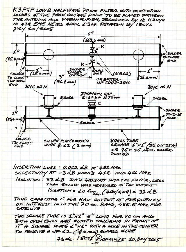
In addition the K3PGP filter supply GaAsFET
protection because it consists of a low Q halfwave transmission
line with two diodes at the peak voltage point and has an
insertion loss of only 0.062 dB at 432 MHz or 435 MHz
depending on the frequency in wich it is tuned and provides the
bonus of adequate selectivity to -3dB points at approximately 412
and 466 MHz to clean up the garbage at most locations. The diodes
are connected back to back in antiparallel at the center of the
halfwave transmission line i.e. at the peak voltage point so that
if accidentally RF power enters from the TX end of the line than
the diodes start to conduct and the center of the filter goes
short circuit. In this condition the halfwave transmission line
looks like two 1/4 wave lines with the common end shorted by the
diodes so that the TX end and the RX end of the lines are showing
very high impedance and with 400 watt into the filter less than
80 mW was measured at the output.
Contruction of the filter is very simple and can
be described. Get a brass square tubing 1" x 1" ( 25.4
mm) and 6" long (152.4 mm) Prepare two 1" x 1"
square plates from brass-sheet and for both drill a
2 mm hole in the center of it.
One side of the square tubing is large 1" x 6" and it must receive 3 longitudinal holes.
A center hole diameter 15/64 (6 mm) is to receive an air variable capacitor type MAV03A10 Microelectronics or similar from Johanson 0.8 to 10 pF and Q > 5000 at 100 Mhz
Another hole must be centered 1" (25.4 mm) from one end of the square tube to receive a connector and the diameter of this hole depends if a BNC or N connector is used for it.
Similarly another hole must be drilled 1" (25.4 mm) from the other end of the square tubing.
After the mechanical parts are cutted and drilled it is best to silver plate all parts for better performance.
Instead to use screws to fasten the flange of connectors it is best to tinsolder the flange to the square tube at this point.
Now slip the air capacitor inside the square tube and screw up the nutoutside the 15/64 (6 mm) hole.
Get two diodes 1N914's or better of the HP 5082-2800 series and solder the anode of one diode and the cathode of the other diode to the capacitor stud.
Working inside the square tube is difficult and solder the other ends of the diodes to ground inside of the tube is not easy so that it is best to drill two small holes in the wall of the square tube and solder the terminals of the diodes to ground simmetrically outside.
Now get a # 12 AWG (2 mm) silver plated copper wire at least 8" (20 cm) long.
Slip it into the tube and solder the wire to the capacitor stud and to both
the central pins of the input and output connectors.
Now carefully slip the copper wire in to the central hole of one of the 1" x 1" square plate and position the plate to fit the end of the square tube.
Solder the plate with tin along four sides of the square tube including thewire in the center.
Do the same to close the other end of the square tube and solder the wire to the center of the other square plate.
Both connectors can be used for IN and OUT and they can be interchanged. Since the connectors are simmetrically soldered to the center conductor respective to the ground than the impedance of the load connected to one port is seen unchanged to the other port at resonance.
To tune the filter is enough to place it between the antenna and the preamplifier and adjust the capacitor for maximum output.
If an Automatic Noise Figure Meter is available connect the noise head to one port of the filter and the preamplifier to the other port and adjust the capacitor for the lowest Noise Figure. Since the insertion loss of the filter is less than 0.1 dB depending on the quality of used connectors than the overall NF of the system with and without filter should be very small.
The drawing of this filter + preamplifier protection was originally publisched by Al, K2UYH in to the "432 EME NEWS April 1977
I have redrawn it from the original sketch with more details for better understanding
73" de
i8CVS Domenico
Original pages as they appeared in the April 1977 issue thanks to I8CVS!
.
.
Home Astronomy Bicycle Construction Laser Moonbounce Software Guest Misc
Contents of this website are ©1997 - 2014 of K3PGP and of the originating authors.