K3PGP.Experimenter's.Corner
![]()
K3PGP.Experimenter's.Corner
![]()
Home Astronomy Bicycle Construction Laser Moonbounce Software Guest Misc Sales
Radar Echoes From the Moon |
||
Detailed description of the techniques underlying the first recorded radio transmission through outer space. Calculations show that the maximum range of the Signal Corps radar on lunar target exceeds one million miles |
||
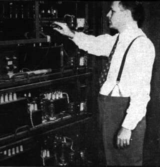
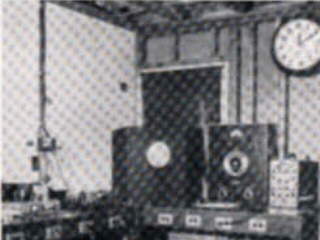
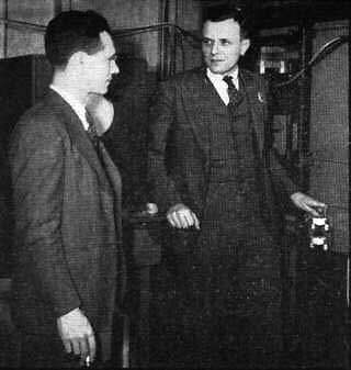 Dr. Harold T. Webb (right) adjusts the auxiliary tuning crystal in the lunar receiver while E. K. Stodola looks on. Behind Stodola is the nine-inch type-A indicator which records the echoes. |
THE RECENT
EXPERIMENTS performed
by the Signal Corps Engineering Laboratories in receiving
radar echoes from the moon have aroused much
comment from engineers, astronomers and others engaged
in technical pursuits. Although the scientific aspects of
sending radio frequency signals through the
ionosphere are certainly of importance, the work done on
the project is better classified as an
engineering achievement. As yet, no long term
systematic observations have been made. This article is
confined, therefore, to a discussion of the
technical characteristics and general description of
the equipment employed. Briefly, the experiment consisted of transmitting quarter second pulses of radio frequency energy at 111.5 mc every four seconds in the direction of the moon, and detecting echo signals approximately 2.5 seconds after transmission. Display of the detected signals was audible as well as visible. Technically, the experiment utilized well established radar techniques, but with radically different constants throughout the system. Considerations of pulse width, receiver bandwidth, transmitter power and the precise frequency of the returned signal due to Doppler effect, were such that careful attention had to be given to the design of the overall equipment. After preliminary calculations were made concerning transmitter power, the reflectivity coefficient of the target, and receiver noise figure, it was apparent that receiving radar echoes from the moon was technically possible. Under the direction of Lt. Col. John H. DeWitt, a project called "project Diana" was set up in September 1945 to develop a radar system capable of transmitting rf pulses to the moon, and detecting echoes more than 2 seconds later. Prior to entering the Signal Corps, Colonel DeWitt, who at that time was chief engineer of Radio Station WSM in Nashville, Tenn., designed and constructed transmitting and receiving equipment for the purpose of receiving echoes from the moon. This equipment employed substantially similar transmitter power and frequency to that used by the Signal Corps, but the attempt was a failure due to insufficient sensitivity in the receiver. Colonel DeWitt's appreciation of the problem and personal supervision were the driving forces that made the present experiment successful. Assisting Lt. Colonel DeWitt were: E. K. Stodola, Dr. Harold D. Webb, Herbert P. Kauffman and the writer, all of Evans Signal Laboratory. Credit is also due the members of the Antenna and Mechanical Design Croup, Research Section, Theoretical Studies Group and others. The practical implications of radar contact with the moon are numerous. During the war the Germans used the V2 Rocket which climbed some 70 miles above the earth, and the future holds the unhappy prospect of missiles going far higher than this. The matter of transmission of radio signals to great distances above the earth for detection and control of such weapons becomes a problem of military importance. Further, the use of a reflector far beyond the earth for radio waves makes possible direct measurement of the ability of radio waves to penetrate the ionosphere. A more complete investigation in this direction is indicated. The possibility of using the moon as the reflector for a part time long distance point to point communication system is also being considered, as well as using the moon as a target to measure field strength patterns. |
|
 Lt. Colonel John H. DeWitt Jr., in charge of the project, a modified version of the SCR-271 early warning radar used at Pearl Harbor. DeWitt is the former chief engineer of WSM. |
||
.
 |
The author, Jack Mofenson, adjusts the position of the waveform monitoring stub. Over this transmission line traveled the 3 kw transmitted pulse and a millionth of a billionth watt echo. |
Determination of Requirements
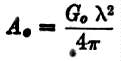
Several of the constants which determine the maximum distance at which a radar set can detect targets are peak transmitter power, radio frequency of the transmitted signal, duration of the signal, receiver noise figure, and target echoing area. These constants, among others, are concisely summarized in what has been called the free space radar equation.
![]() Equation (1)
Equation (1)
This equation has already been derived in Electronics In this equation, r is the radar range at which a signal may be detected, Pt is the transmitter power during the pulse, Go, the transmitting antenna power gain, A. the absorption area of the receiving antenna, o the effective echoing area of the target, and P, the power of a barely discernible signal, on the same basis as Pt. The power gain due to ground reflections (not considered in the freespace equation) at maximum effectiveness increases the range of the system by a factor of 2. This is equivalent to a power gain of 12 db. In the case of a target as large as the moon (2160 miles diameter), calculations showed that in order to receive an echo from the whole hemisphere of the moon at once a pulse width greater than 0.02 seconds was required. This set a lower limit on the transmitter pulse width which corresponds to an optimum bandwidth of 50 cps for the receiver. These requirements eliminate, for the present, the use of the microwave frequencies, because of considerations of pulse length.
 Propagation studies
indicated that electromagnetic waves at a frequency
of 110 mc were capable of penetrating the ionosphere, and
because of availability of equipment, a radar set
operating at 111.5 me was chosen for the experiment. The
peak power available in this transmitter was equivalent
to 3000 watts for Pt
using a 0.25 second pulse. The transmitter had
the added advantage of being crystal controlled,
deriving its final radio frequency after a series of
frequency multiplication from a 516.2 kc crystal oscillator. The
receiver associated with the transmitter was of
the multi mixer type (quadruple superheterodyne) capable
of beating down radio frequency signals to a final
intermediate frequency of 180 cycles per second. Such an
arrangement permitted use of an extremely narrow pass
band, 57 cps, thus making the receiver highly selective and limiting
the noise to a very low value. The extremely narrow band
receiver was an advantage, also, because it permitted tuning the
receiver to the exact radio frequency of the returned
echo. The importance of this can best be realized by
considering the fact that due to the relative velocities of the
earth and the moon, the returned signal may differ from
the transmitted signal by as much as 300 cycles, due to
the Doppler frequency shift. In using a highly selective
receiver whose final mixer is tuned to receive the
precalculated frequency of an echo return from the moon, the
receiver rejects any signal returned at any other
frequency. To reduce the noise contribution of the
receiver, a high gain, low noise figure preamplifier was
connected between the antenna and the receiver proper.
The minimum perceptible received power was P,
readily calculated from the formula for noise figure.
Propagation studies
indicated that electromagnetic waves at a frequency
of 110 mc were capable of penetrating the ionosphere, and
because of availability of equipment, a radar set
operating at 111.5 me was chosen for the experiment. The
peak power available in this transmitter was equivalent
to 3000 watts for Pt
using a 0.25 second pulse. The transmitter had
the added advantage of being crystal controlled,
deriving its final radio frequency after a series of
frequency multiplication from a 516.2 kc crystal oscillator. The
receiver associated with the transmitter was of
the multi mixer type (quadruple superheterodyne) capable
of beating down radio frequency signals to a final
intermediate frequency of 180 cycles per second. Such an
arrangement permitted use of an extremely narrow pass
band, 57 cps, thus making the receiver highly selective and limiting
the noise to a very low value. The extremely narrow band
receiver was an advantage, also, because it permitted tuning the
receiver to the exact radio frequency of the returned
echo. The importance of this can best be realized by
considering the fact that due to the relative velocities of the
earth and the moon, the returned signal may differ from
the transmitted signal by as much as 300 cycles, due to
the Doppler frequency shift. In using a highly selective
receiver whose final mixer is tuned to receive the
precalculated frequency of an echo return from the moon, the
receiver rejects any signal returned at any other
frequency. To reduce the noise contribution of the
receiver, a high gain, low noise figure preamplifier was
connected between the antenna and the receiver proper.
The minimum perceptible received power was P,
readily calculated from the formula for noise figure.
![]() Equation (2)
Equation (2)
In this formula E2/4R is the maximum available signal power at the receiver input terminals in watts, where E is the signal voltage at the antenna terminals, and R is the effective impedance in ohms. KTB is the maximum available noise power at the receiver input, where K is Boltzman's constant, 1.37 X 10⁻²³ joules per degree Kelvin, T is the temperature in degrees Kelvin, chosen, at 300 degrees, and B is the noise bandwidth of the receiver in cycles per second. For this receiver B is 57. For a one to one ratio Eq. 3 gives signal power to noise power of
![]() Equation (3)
Equation (3)
1.48 X 10⁻¹⁸ watts, taking the effective noise figure of the receiver as 7 db.
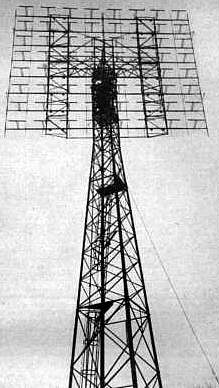
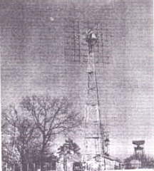
The best antenna available at this frequency was a 32 dipole array utilized by the SCR-271 early warning radar. Two of these arrays were secured side by side and mounted on a 100 foot tower. Calculations show that the array had a power gain of 152 times that of a single halfwave dipole antenna. Since the effective gain of a single dipole is 1.64 times that of an isotropic radiator, the value of G. is given as 1.64 X 152 or 250.
The absorption area A, of the
receiving antenna is calculated from
 Equation (4)
Substituting the value of G, previously given, Ao = 522.1 X 10⁻⁷ square miles. The remaining constant to be determined before solving Eq. 1 is o the effective echoing area of the target. Calculations of the reflectivity coefficient made by Walter McAfee of the Theoretical Studies Group, assuming zero conductivity and a dielectric constant of six for the moon, resulted in the figure 0.1766. The effective echoing area is this figure multiplied by the projected area of the moon, Pi d2/4 where d is the lunar diameter. This gave an effective echoing area of 0.1766 (2160)2 (3.1416)/4 or 647,000 square miles.
Substitution of these values in the free space radar equation gave a maximum range of 573,500 miles and indicated that the effective range of the equipment chosen was more than twice that needed to receive echoes from the moon. By adding the power gain due to ground reflection, a further excess of power of 12 db or a range of 1,140,000 miles was indicated, which meant that according to calculations, the received signal should be about 20 db above thermal noise. This calculation of the signal strength of the returned echo checked closely with observations and indicated that no appreciable attenuation occurs in free space.
Transmitter
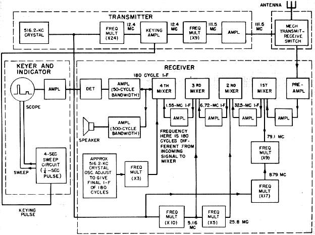
Once the determination of constant was completed, the choice of available radar sets was made. Since no attempt was made to design major components specifically for this experiment, the selection of receiver and transmitter was made from equipment on hand. A crystal controlled radar transmitter and receiver designed by Major E. H. Armstrong for another purpose were selected since they met the requirements of power and bandwidth. A block diagram of the complete transmitting, receiving and indicating system is shown in Fig. 1.
The transmitter is crystal controlled, deriving its final radio frequency of 111.5 me after a series of frequency' multiplications from a fundamental crystal oscillator frequency of 516.2 kc.
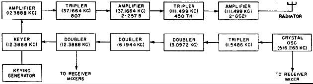
Keying is accomplished by causing a low level multiplier stage to conduct by driving its cathode negative for the duration of the transmitted pulse. In the initial setup, keying was performed mechanically by a relay, but this has since been replaced by an electronic keyer with the pulse width controllable between 0.02 to 0.2 seconds. A block diagram of the transmitter is shown in Fig. 2.
From the diagram it is apparent that the transmitter is of a conventional type. The output is fed over a 250 ohm open wire transmission line to the antenna array. The antenna contains 64 dipoles horizontally polarized. The effective power gain of the array is 250, or 24 db. The antenna, shown in Fig. 3; is mounted on a steel tower 100 feet high and is controllable in azimuth only. No provision has been made to incline the antenna in elevation. Because of this restriction, the times of observation using the present equipment were necessarily limited to moonrise and moonset. That this condition of observation is the worst possible (due to the long path through the atmosphere and the consequent possibility of trapped radiation) has been recognized. But it was impractical to procure an array of the equatorial type. Aside from propagation deficiencies, a far more serious limitation was the fact that observations were limited to two short periods daily.
 The beam width of the
array is approximately 15 deg at the half power points,
with the first three lobes spaced approximately 3 deg in
elevation. Since the diameter of the moon subtends
roughly one half degree of arc, most of the power
transmitted does not illuminate the target, which constitutes
a serious waste of power. The rate of rise of the moon
along its ecliptic is 1 degree of arc every 4 minutes,
which allowed roughly 40 minutes of observation as the
moon intercepted the first three lobes of the
antenna. Bending effects due to long transmission path
through the ionosphere undoubtedly exist, but no precise
measurement of this effect has yet been made.
The beam width of the
array is approximately 15 deg at the half power points,
with the first three lobes spaced approximately 3 deg in
elevation. Since the diameter of the moon subtends
roughly one half degree of arc, most of the power
transmitted does not illuminate the target, which constitutes
a serious waste of power. The rate of rise of the moon
along its ecliptic is 1 degree of arc every 4 minutes,
which allowed roughly 40 minutes of observation as the
moon intercepted the first three lobes of the
antenna. Bending effects due to long transmission path
through the ionosphere undoubtedly exist, but no precise
measurement of this effect has yet been made.
Receiving System
The receiving system is sufficiently different from conventional design to warrant a more complete description. A block diagram is shown in Fig. 4. The entire receiver is frequency controlled, and contains four mixer stages which heterodyne the radio frequency signal to a final intermediate frequency of 180 cps. Since the first three injection frequency voltages as well as the final radio frequency are derived from multiples of common crystal oscillator, a high degree of frequency stability is achieved in the system. This high degree of stability is essential to permit tuning the highly selective receiver to the frequency of the echo signal. This tuning is accomplished in the final heterodyne stage.
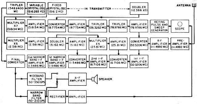
In tuning it is necessary to take account of the change in frequency of the returned signal which results from variations in the relative velocity of the moon with respect to the earth. The frequency of the returning echo may differ from the transmitted frequency by as much as 300 cycles per second, since the relative velocities of the earth and moon vary from about +900 mph at moonrise to -900 mph at moonset. At the frequency of the transmitter, a relative velocity of 3 miles per hour between antenna and target causes a shift of approximately 1 cycle per second in the received signal. This frequency shift, due to relative velocities of the transmitting antenna and target, is present in all radar echoes from moving targets, but is undetected in conventional receivers because the band width of the normal receiver is many times greater than the frequency shift. In the Diana receiver, a band width of 57 cps is achieved in the final IF stages. It is therefore necessary to predetermine the Doppler frequency shift for the particular observation being made, and to select the proper crystal for the final heterodyne mixer. To achieve the high degree of accuracy required in the final mixer, provision is made to modify the frequency of the crystal controlled oscillator by means of a screwdriver control which varies the air gap above the crystal. Final adjustment of the oscillator is made by beating the crystal oscillator output against a secondary frequency standard source, and observing the output on a monitoring oscilloscope.
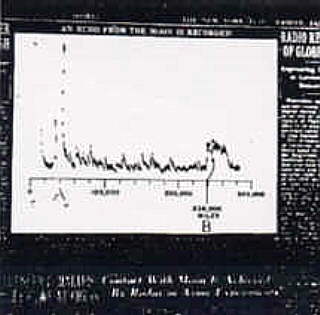 |
The output of the final heterodyne mixer is fed into two channels, one audio, the other video. The audio channel is simply a power amplifier stage with the output connected to a loud speaker. The video output channel is fed into a second detector to recover the envelope of the 180 cps intermediate frequency signal, and then is amplified by a high gain video amplifier and connected directly to the vertical deflecting plates of a nine inch cathode ray tube. The horizontal deflection is a linear 4 second type A sweep. The visible output is the characteristic low frequency noise pattern representing a 57 cycle bandwidth centered at 180 cycles. A sudden upward departure from the base line occurs when an echo signal is received from the moon. This is shown clearly in the photo at left. The audible signal is random noise of 57 cycle bandwidth, superimposed on a fixed frequency note, at the intermediate frequency of 180 cycles, when the echo is received. |
As stated previously, tuning of the receiver is accomplished in the final mixer. The injection signal frequency must be calculated for each observation to take into account the
relative velocity of target and antenna due to both the rotational velocity of the earth and the orbital velocity of the moon. These data, together with azimuth angle and time, are calculated daily from information given by the Nautical Almanac and Ephemeris. The detection of the frequency due to Doppler shift is made with a high degree of accuracy by the selective receiver. This in itself is corroboration that the echo signal is from the moon. Also, the echo interval of 2.4 seconds admits of no other explanation.
The pre amplifier of the receiver consists of a three stage tuned rf amplifier employing two grounded grid stages (654) followed by a 6SH7 tuned amplifier at the transmitter frequency. The overall gain of the pre amplifier alone is 30 db with an overall noise figure of 3.5 db and a bandwidth of 1 mc. The electrical design of the first two stages was suggested by a development of Dr. F.B. Llewellyn. A simplified schematic of the first two stages is shown in Fig. 6. The use of concentric tubing inductances for the tuned circuits provides automatic rf filtering on the direct current and filament leads. The preamplifier was designed originally as an improvement kit for the SCR-271 radar, and like the transmitter and receiver, was chosen for the Diana experiment because it satisfied one of the requirements, that of a very low noise figure receiver. A tuned impedance matching transformer is used between the receiver and transmission line to convert the 250 ohm balanced input to the 50 ohm unbalanced input of the preamplifier.
The transmit receive switching system (t/r box) employed in the original experiment was a set of two mechanically operated shorting bars on the transmission line, operating from a multivibrator controlled relay during the transmitted pulse interval of 0.25 sec. One of the shorting bars serves to short out the receiver input during transmission, and the other shorts out the transmitter during reception.
Keyer and Indicator
The visual indicator used is a nine inch electrostatic cathode ray tube, 9EP7, with a long persistence screen. The electron beam is caused to scan the width of the tube, synchronously with the transmitted pulse, in 4 seconds, forming a linear time base. The persistence of the tube is long enough to retain the pattern for at least two sweeps. The circuit employed to generate this sweep is a direct coupled transitron sawtooth oscillator, described below. A pulse equivalent in time to the keying pulse is also generated by this circuit and is applied to the cathode of a low level multiplier stage of the transmitter, causing it to conduct for the pulse duration and to drive the subsequent multipliers.
The time base generator consists essentially of a high gain pentode amplifier with capacitance coupling between plate and grid. The schematic is shown in Fig. 7. The capacitance coupled path includes a cathode follower stage, the left hand section of V2 For the duration of the conduction cycle, the anode voltage of the pentode V1, drops and capacitor C1, begins to discharge through the tube. As the voltage on the plate drops the current flow in C1, drives the grid negative, tending to cut off the plate current. A condition of dynamic equilibrium then exists with the plate voltage dropping at a linear rate determined by R1, and C1, and the grid being maintained at a constant voltage, since each decrement in plate voltage causes a corresponding drop on the grid which keeps the grid signal and hence the output of the tube substantially constant. The time constant of R1, C1, is chosen to cause C1, to become fully discharged during the cycle.
When the plate voltage drops to the point where electrons from the cathode can no longer flow to it, an increase in screen current occurs which rapidly decreases the screen voltage and correspondingly decreases the suppressor voltage. This action, which is cumulative, has the effect of suddenly cutting off the anode current. This causes the cathode current to be retarded by the suppressor grid and made to flow to the screen. A negative pulse appears at the screen, and C1, begins to charge through the cathode follower until a point is reached where the plate begins to draw current and the oscillator is recycled. The screen returns to its original voltage, and the plate voltage begins to fall. By suitable choice of R1, and C1, a range of from about 0.1 to 3 cps is obtained.
Keying voltage signals are derived from the differentiated output of the negative pulse appearing on the screen of the oscillator. This is used to trigger a multivibrator whose time constant is controllable by a variable 5 meg resistor, varying the output pulse width from 0.02 to 0.25 seconds.
The addition of the cathode follower stage V2,was made to shorten the charge time of C1, by causing it to charge through the grid cathode space of the cathode follower. This reduces the return trace time. Tube V3, serves as a degenerative phase inverting amplifier to secure push pull sweep voltage.
The keyer multivibrator is a conventional cathode coupled flip flop circuit with the initiating trigger applied as a positive pulse on the grid of the normally nonconducting section. A positive pulse varying in width from 0.02 to 0.85 seconds is obtained at the plate of the other section. This signal is applied to a normally cut off pentode whose load impedance is the cathode of the 12.388 me amplifier stage in the transmitter. For the duration of this applied signal, the plate of the amplifier is driven negative, taking the cathode of the keying tube down with it, thus causing it to conduct.
The first echoes from the moon were received at moonrise on January 10, 1946. The indication was of the audible type in the form of a 180 cycle beat note occurring 2.5 seconds after transmission. Although numerous observations have been made, both at moonrise and moonset, echo returns do not occur after every transmission. Further measurements are needed before precise scientific conclusions can be drawn.
Additional Photos
 |
|
|
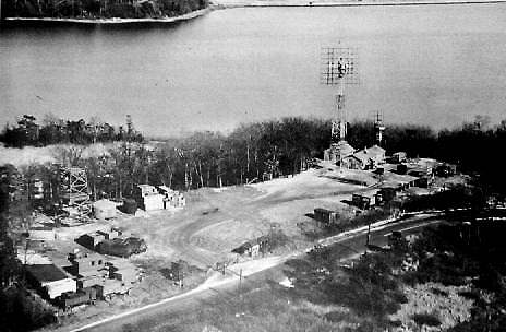
Antenna |
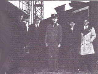
Left to right, J. Mofensen, Dr. H. Webb, Lt.
Col. J. R. DeWitt, ex-W4FU, E. K. Stodola, W3IYF, H. P. Kauffman, W2OQU. |
Modified SCR-271 Radar Transmitter |
.
 |
Some of the apparatus associated with the experiment |
LIVE 1946 broadcast from WOR radio >
WOR
- 1946
You can hear some interference to the
audio from the transmitter keying plus a few of the actual
echoes!
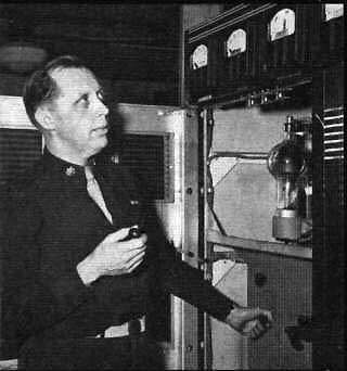
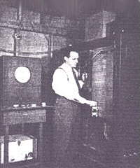
| Herbert Kaufman, W2OQU adjusting the control of the variable air-gap crystal holder that sets the fourth heterodyne of the receiver to the proper frequency to compensate for Doppler effect. |
 |
REFERENCE
(1)
The Radar Equation, Electronics p. 92, April 1945
Home Astronomy Bicycle Construction Laser Moonbounce Software Guest Misc Sales
Contents of this website are ©1995-2012 of K3PGP and of the originating authors.